 |
| Home │ Audio
Home Page |
Copyright © 2011 by Wayne Stegall
Created December 14, 2011. See Document History at end for
details.
Transistor Preference
The effect of
transistor choice on distortion performance
Introduction
Some time ago, I simulated a change in the Simplest Voltage-feedback Op-Amp of the article Musical Feedback Amplifiers. I changed the small signal bipolar output transistor to a power MOSFET to determine its suitability as a headphone amplifier. Oddly, the second harmonic was nearly canceled out in a simulation on LTSpice. I thought it well to evaluate different transistor choices in the same amplifier topology.Presumptions
It would seem that choice of transistor would not be fixed but fall to the strengths and weaknesses that each have in a particular circuit context.| Advantages |
Disadvantages |
|
| Bipolar |
|
|
| Square Law Devices |
|
|
Topology Design
Due to progressive increase in signal as it passes through each gain
stage, transistors closer to the output are expected to contribute more
to the distortion characteristic than those closer to the input.
Therefore the topology is expected to affect the distortion outcome in
the following ways:- The single-ended output stage is expected to contribute predominantly second then lower levels of higher harmonics.
- The differential input is expected to produce odd harmonics dominated by the third.
- Biasing the tail of differential pair with a resistor is expected to create common-mode gain which will produce single-ended distortion products as the output stage does, only lower in quantity.
- All circuits are powered by ±15V supplies.
- The output stages are biased at 100mA to keep transistor
dissipation across 15V at 1.5W. This is the typical power
dissipation that a power transistor is capable of without a heat
sink. Then a small TO-220 heat sink could be added for extra
thermal safety.
- Compensation was omitted. I anticipated that the higher capacitance of power transistors would create the dominant pole in the output stage. AC analysis showed no oscillation of any of the uncompensated circuits.
- These circuits are for illustration only. Practical designs
would
require output current limiting and/or an output resistor in the range
of 50-100Ω and optionally a dc servo. Then they could become a
combination headamp/preamp with a switch to select output to headphones
or amplifier.
Simulation Methodology
I decided to represent the distortion graphically by plotting transfer curve error.1 This was done by subtracting a distortionless transfer curve from the distorted one to leave only the shape of the error to examine. Otherwise, unaltered transfer curves with low distortion would visibly appear straight. The Fourier transform is then given to reveal additional detail.Circuit 1
Design Theory
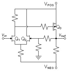
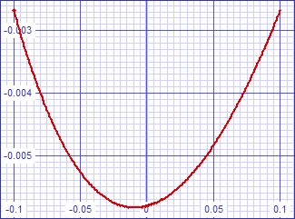
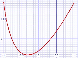
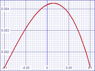
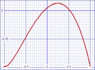
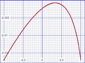
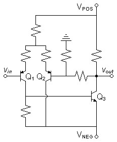
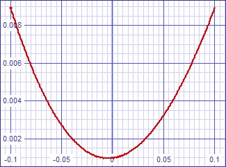
All square-law devices. Subjective preference for square law devices.| Schematic | Transfer Curve Error for 1VPEAK into 32Ω | Transfer Curve Error for 10VPEAK into 600Ω |
 |
 |
 |
Fourier analysis for vout:
No. Harmonics: 16, THD: 0.0391661 %, Gridsize: 200, Interpolation Degree: 3
| Harmonic | Frequency | Magnitude | |
Norm. Mag | |
Percent | |
Decibels |
|
|
|
|
|
|
|
|||
| 1 | 1000 | 0.24621 | 1 | 100 | 0 | |||
| 2 | 2000 | 0.000096406 | 0.00039156 | 0.039156 | -68.1440 | |||
| 3 | 3000 | 2.1992E-06 | 8.93219E-06 | 0.000893219 | -100.981 | |||
| 4 | 4000 | 6.30358E-08 | 2.56024E-07 | 2.56024E-05 | -131.834 | |||
| 5 | 5000 | 2.02717E-09 | 8.2335E-09 | 8.2335E-07 | -161.688 | |||
| 6 | 6000 | 6.98379E-11 | 2.83651E-10 | 2.83651E-08 | -190.944 | |||
| 7 | 7000 | 2.47659E-12 | 1.00588E-11 | 1.00588E-09 | -219.949 | |||
| 8 | 8000 | 2.48692E-13 | 1.01008E-12 | 1.01008E-10 | -239.913 | |||
| 9 | 9000 | 2.48044E-13 | 1.00745E-12 | 1.00745E-10 | -239.936 | |||
| 10 | 10000 | 1.24436E-13 | 5.05407E-13 | 5.05407E-11 | -245.927 | |||
| 11 | 11000 | 4.99582E-13 | 2.02909E-12 | 2.02909E-10 | -233.854 | |||
| 12 | 12000 | 2.2006E-13 | 8.93788E-13 | 8.93788E-11 | -240.975 | |||
| 13 | 13000 | 6.9418E-13 | 2.81946E-12 | 2.81946E-10 | -230.997 | |||
| 14 | 14000 | 5.74541E-13 | 2.33354E-12 | 2.33354E-10 | -232.64 | |||
| 15 | 15000 | 5.98942E-13 | 2.43264E-12 | 2.43264E-10 | -232.278 |
Circuit 2
Design Theory
Bipolar output is configured as current amplifier because resistor bypassing VBE shunts fairly constant current due to almost constant voltage there. Hope transfer curve of differential FET front end passes through little changed.| Schematic | Transfer Curve Error for 1VPEAK into 32Ω | Transfer Curve Error for 10VPEAK into 600Ω |
 |
 |
 |
Fourier analysis for vout:
No. Harmonics: 16, THD: 0.05023 %, Gridsize: 200, Interpolation Degree: 3
| Harmonic | Frequency | Magnitude | |
Norm. Mag | |
Percent | |
Decibels |
|
|
|
|
|
|
|
|||
| 1 | 1000 | 0.199075 | 1 | 100 | 0 | |||
| 2 | 2000 | 9.97235E-05 | 0.000500934 | 0.0500934 | -66.0044 | |||
| 3 | 3000 | 1.74896E-06 | 8.78545E-06 | 0.000878545 | -101.125 | |||
| 4 | 4000 | 2.34085E-06 | 1.17586E-05 | 0.00117586 | -98.5929 | |||
| 5 | 5000 | 1.77116E-06 | 8.89695E-06 | 0.000889695 | -101.015 | |||
| 6 | 6000 | 2.38499E-06 | 1.19803E-05 | 0.00119803 | -98.4306 | |||
| 7 | 7000 | 1.76116E-06 | 8.8467E-06 | 0.00088467 | -101.064 | |||
| 8 | 8000 | 2.37402E-06 | 1.19252E-05 | 0.00119252 | -98.4707 | |||
| 9 | 9000 | 1.7459E-06 | 8.77005E-06 | 0.000877005 | -101.14 | |||
| 10 | 10000 | 2.35965E-06 | 1.18531E-05 | 0.00118531 | -98.5234 | |||
| 11 | 11000 | 1.72756E-06 | 8.67794E-06 | 0.000867794 | -101.232 | |||
| 12 | 12000 | 2.34179E-06 | 1.17633E-05 | 0.00117633 | -98.5894 | |||
| 13 | 13000 | 1.7066E-06 | 8.57266E-06 | 0.000857266 | -101.338 | |||
| 14 | 14000 | 2.32027E-06 | 1.16552E-05 | 0.00116552 | -98.6696 | |||
| 15 | 15000 | 1.68354E-06 | 8.45681E-06 | 0.000845681 | -101.456 |
Circuit 3
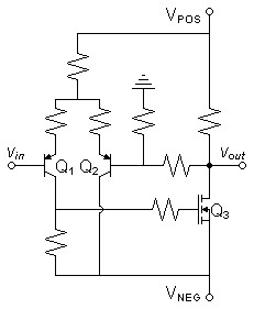
Design Theory
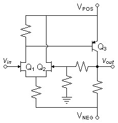
Local feedback will reduce distortion of PNP front end sufficient to allow square law characteristic of output MOSFET to dominate transfer characteristic.| Schematic | Transfer Curve Error for 1VPEAK into 32Ω | Transfer Curve Error for 10VPEAK into 600Ω |
 |
 |
 |
Fourier analysis for vout:
No. Harmonics: 16, THD: 0.0242139 %, Gridsize: 200, Interpolation Degree: 3
| Harmonic | Frequency | Magnitude | |
Norm. Mag | |
Percent | |
Decibels |
|
|
|
|
|
|
|
|||
| 1 | 1000 | 0.249344 | 1 | 100 | 0 | |||
| 2 | 2000 | 6.02183E-05 | 0.000241507 | 0.0241507 | -72.34140554 | |||
| 3 | 3000 | 9.48489E-07 | 3.80394E-06 | 0.000380394 | -108.3953268 | |||
| 4 | 4000 | 1.31238E-06 | 5.26333E-06 | 0.000526333 | -105.574788 | |||
| 5 | 5000 | 7.22139E-07 | 2.89616E-06 | 0.000289616 | -110.763549 | |||
| 6 | 6000 | 1.07926E-06 | 4.3284E-06 | 0.00043284 | -107.2734522 | |||
| 7 | 7000 | 1.54848E-06 | 6.21022E-06 | 0.000621022 | -104.1378603 | |||
| 8 | 8000 | 1.03186E-06 | 4.13829E-06 | 0.000413829 | -107.6635816 | |||
| 9 | 9000 | 1.01281E-06 | 4.06189E-06 | 0.000406189 | -107.8254368 | |||
| 10 | 10000 | 3.72702E-07 | 1.49473E-06 | 0.000149473 | -116.508745 | |||
| 11 | 11000 | 2.19296E-06 | 8.79495E-06 | 0.000879495 | -101.1153325 | |||
| 12 | 12000 | 5.6078E-07 | 2.24903E-06 | 0.000224903 | -112.960095 | |||
| 13 | 13000 | 1.56394E-06 | 6.27222E-06 | 0.000627222 | -104.0515743 | |||
| 14 | 14000 | 1.60973E-07 | 6.45586E-07 | 6.45586E-05 | -123.8009179 | |||
| 15 | 15000 | 1.57123E-06 | 6.30146E-06 | 0.000630146 | -104.0111763 |
Circuit 4
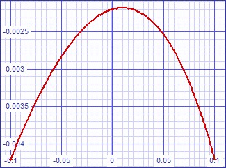
Design Theory
All bipolar. Added for completeness of overall analysis. Not a subjective preference at all.| Schematic |
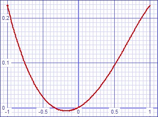
Transfer Curve Error for 1VPEAK into 32Ω | Transfer Curve Error for 10VPEAK into 600Ω |
 |
 |
 |
Fourier analysis for vout:
No. Harmonics: 16, THD: 0.155365 %, Gridsize: 200, Interpolation Degree: 3
| Harmonic | Frequency | Magnitude | |
Norm. Mag | |
Percent | |
Decibels |
|
|
|
|
|
|
|
|||
| 1 | 1000 | 0.176268 | 1 | 100 | 0 | |||
| 2 | 2000 | 0.000241366 | 0.00136931 | 0.136931 | -57.27 | |||
| 3 | 3000 | 9.59125E-05 | 0.000544128 | 0.0544128 | -65.286 | |||
| 4 | 4000 | 9.43285E-06 | 5.35142E-05 | 0.00535142 | -85.4306 | |||
| 5 | 5000 | 0.000048478 | 0.000275024 | 0.0275024 | -71.2126 | |||
| 6 | 6000 | 1.37704E-05 | 7.81217E-05 | 0.00781217 | -82.1446 | |||
| 7 | 7000 | 3.87223E-05 | 0.000219678 | 0.0219678 | -73.1643 | |||
| 8 | 8000 | 1.06449E-05 | 6.03902E-05 | 0.00603902 | -84.3807 | |||
| 9 | 9000 | 4.63376E-05 | 0.000262882 | 0.0262882 | -71.6048 | |||
| 10 | 10000 | 1.83984E-05 | 0.000104378 | 0.0104378 | -79.6278 | |||
| 11 | 11000 | 1.74559E-05 | 9.90305E-05 | 0.00990305 | -80.0846 | |||
| 12 | 12000 | 1.37368E-05 | 7.79313E-05 | 0.00779313 | -82.1658 | |||
| 13 | 13000 | 1.38975E-05 | 0.000078843 | 0.0078843 | -82.0647 | |||
| 14 | 14000 | 9.32876E-06 | 5.29237E-05 | 0.00529237 | -85.527 | |||
| 15 | 15000 | 6.42674E-06 | 0.00003646 | 0.003646 | -88.7637 |
Conclusions
I was surprised at the visible similarity of the transfer curve error graphs for all combinations of transistor choices. This suggests that the topology itself favors the predominance of second and third harmonics. The 1VPEAK output error plots driving 32Ω were near parabolas indicating predominance of the second harmonic. That the 10Vpeak output error plots, driving 600Ω, were offset to one side more than the other plots shows the third harmonic increasing faster with level than the second.The pattern of harmonics beyond the third favors the all-FET design, where they fell to vanishing levels. In the case of a bipolar output with bias resistor bypassing VBE, it may have been an oversimplification to presume the bypass resistor bypasses nearly constant current. In reality, the bypass resistor passes relatively unchanging current proportional to the logarithm of the current going into the base, perhaps contributing to low levels of higher harmonics that seem not to diminish. The differential bipolar input stage with MOSFET output seems to produce lingering higher harmonics as well. Paradoxically, the all bipolar circuit seems to have a better distortion profile than the mixed transistor circuits, although at a generally higher level. In the end, concern over the low level harmonics would be in vain if masked by the higher level second and third harmonics, as they all appear to have smooth one-bend curves. Beware too the occasional oddity, as the cancelation of the second harmonic in the all-FET circuit that inspired this article.
Still, I would still prefer the subjectively favored all-FET circuit on these objective grounds after all.
|
|
1See article Transfer
Curve Shape and
Distortion
Document History
December 14, 2011 Created.