 |
| Home │ Audio
Home Page |
Copyright © 2010 by Wayne Stegall
Updated March 11, 2010. See Document History at end for details.
Line Level Class A Power Supply
This is an example only. It is not intended to be final or
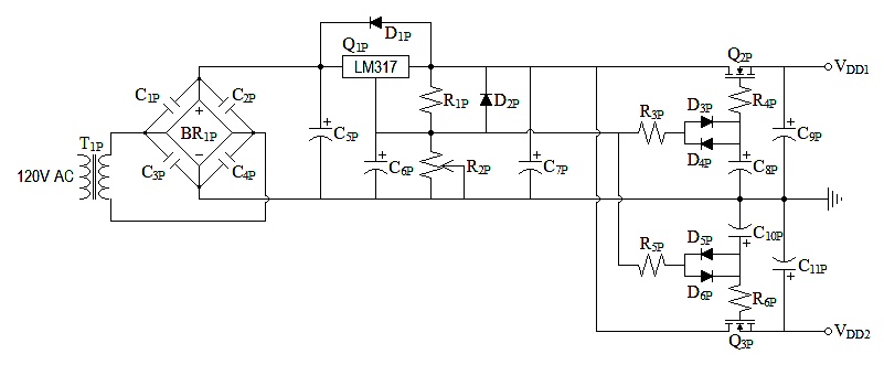
complete design.| Figure
1:
Schematic |
||||||||||||||||||||||||||||||||||||||
 |
||||||||||||||||||||||||||||||||||||||
|
Initial Design Decisions
- The power supply is designed to be simple source follower type
for class-a friendly output impedance.
- Prefiltering is by LM317 for better line regulation. LM317 circuit design is as recommended by datasheet.
- Unique design element pertains to adding parallel diodes to gate circuit of source follower. The diodes create a variable RC constant. This provides for quick charge through the resistor to nearly the desired gate voltage then a slow increase to an enormous RC time constant to hold a constant gate voltage.
- Load requirements: 27.9778112mA out of VDD1, 19.4563897mA out of VDD2.
Calculations
Some of the component choices are not very critical, but I chose to calculate these.- Calculate transformer specification.
Round up to standard value of 20V.
- Calculate C5P for ripple of 0.5V.
iLM317-INPUT = iDD1 + iDD2 + iR1P + iADJ-LM317 = 27.9778112mA + 19.4563897mA + 5mA + 100µA = 52.5342009mA
| C5P = |
i
fΔv |
= |
52.5342009mA
60Hz x 0.5V |
= 1.75114003mF |
- Choose R3P,R5P and C8P,C10P for a time constant of one second.
| vNOISE-C8P-TOTAL = sqrt |
 |
kT
C |
 |
= sqrt |
|
1.3806504e-23 x 298.15ºK
220µF |
|
= 4.325615651nV |
As a matter of curiosity, the 1N914 specification of 5nA reverse current at 20V suggests an ac impedance of 800MΩ at very low ac voltages. (This is due to leakage resistance. Ideal calculated reverse current is very much lower.) 220µF x 400MΩ gives a settled time constant of 88,000 seconds. Because this is such a large value, I suspect it to be very imprecise.
- Establish lower boundary for C9P,C11P based on these criteria:
IRF510 specification: gfs = 1.3S @ 3.4A.
Calculate MOSFET constant from gfs@iD specification.
| kn = | gfs2
4iD |
= |
1.3S2
4(3.4A) |
= 124.2647059mA/V2 |
Recalculate gfs for specific iD.
gfs = 2 x sqrt(kniD) = 2 x sqrt(124.2647059mA/V2 x 27.9778112mA) = 117.9263241mS
| Rout-Q2P = |
1
gfs |
= |
1
2 x sqrt(kniD) |
= |
1
2 x sqrt(117.9263241mS x 27.9778112mA) |
= 8.70477913Ω |
| C9P = |
1
2πfpoleRout-Q2P |
= |
1
2π x 2Hz x 8.70477913Ω |
= 9.14181398mF |
Choose C9P = 10,000µF and solve for the pole frequency.
| fpole = |
1
2πC9PRout-Q2P |
= |
1
2π x 10mF x 8.70477913Ω |
= 1.828362796Hz |
| Figure 2: Bode plot
representing suppression of MOSFET non-linearity by chosen bypass capacitor of 10,000µF |
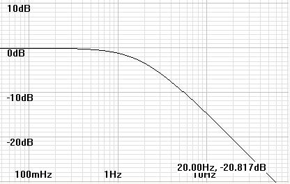 |
A more common choice of 1000µF gives a pole frequency of 18.28362796Hz. This choice may give a slight increase in low bass distortion, and perhaps why some reviewers hear mid-bass bloom in some class A equipment.
VDD2 drives a circuit (source follower) which is relatively insensitive to power supply fluctuations. Therefore you can choose a more arbitrary value here. Save money here to buy a larger C9P.
I choose C11P = 3300µF.
|
|
Document History
January 5, 2010 Created
January 5, 2010 Replace vague load specifications with
exact ones from article JFET Phono Preamp
- Active Inductor Example and update calculations.
March 11, 2010. Corrected for improper gfs
presumptions.