Copyright © 2009 by Wayne Stegall
Updated October 13, 2010. See Document History at end for details.
Basic
Electronics
Power Supply
Ripple Calculations and Capacitor Size
Figure
1:
Graph
of
full-wave
rectification
with
capacitor ripple
|
|
The peak voltage from a
transformer (1.414 x V
rms) has to be derated by the ripple
voltage and diode drop before furthur power supply calculations can be
done.
Ripple calculations are derived from the capacitor formula.
Because this formula is common and important, it may be better to
remember the capacitor formula
Begin with the capacitor formula
(current = capacitance x rate of change of voltage)
Change instantaneous slope
(δv/δt) to constant slope
over finite
interval (Δv/Δt) and solve it
for voltage change.
Where Δv is ripple voltage, i is
load current, Δt is ripple interval (1/120 s for full wave
rectification and 1/60 s for half wave at 60Hz line frequency),
and C is capacitance.
It may be more convenient to relate
Δt as frequency instead. Substitute 1/f for Δt in equation (2).
Now f represents ripple
frequency (120Hz for full wave rectification and 60Hz for half wave
rectification)
Example:
Given full wave rectification, a load current of 3.5A, and a
capacitance of 6800µF, calculate the ripple voltage.
From equation (3)
|
Δv = |
3.5A
120Hz x 6800µF |
=
4.29V
|
As for the thought that lead to this
article. Reading that 47
Labs used 1000µF in its Gaincard amplifier power supplies
puzzled me. Do more powerful amplifiers require larger
capacitors? On first impression it seems so. However, lets
rearrange our ripple equation again.
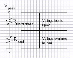
Δv/i is in the form of a
resistance. Ripple voltage increases
with output current just like a voltage drop due to an output impedance
would. The limitation on the useful output of the raw power
supply could be modeled as an equivalent output resistance. This
would not be a real model but an abstraction to aid viewing the concept
in a useful way. It
would be clear then that the percent ripple would be the same into a
constant load (as the 4 to 8Ω of an audio amplifier load) regardless of
the supply voltage (and therefore maximum power). In cases where
a low feedback factor in the amplifier causes concern regarding hum, a
fixed ripple calculation would still be more valid.
Figure 2: Schematic of
ripple abstraction
|
|
The equivalent output impedance with
the above mentioned 1000µF
filter capacitors is:
From equation (4)
|
Δv
i
|
=
|
1
120Hz x 1000µF |
= 8.33Ω |
You can immediately imagine a voltage
divider with respect to an 8Ω load that would give more ripple than
maximum voltage signal. In this case the designer sacrificed a
great deal of power to get something else in return. All
capacitors have stray inductance that compromises their high frequency
regulation ability. (They actually act more like inductors above
their resonant frequency, f = 1/(2
πsqrt(LC)))
The factors
involved in increasing
capacitance increase this stray inductance as well (at least in the
construction of electrolytic capacitors). Power supply speed is
the quest of this engineer. In theory, stray inductance
could be minimized in conjunction with a large capacitance by
paralleling smaller capacitors because paralleling reduces inductance
while increasing capacitance (You can verify the math.). It is
convenient to this end that low-esr capacitors tend to be found in
smaller values. Paralleling small capacitors having better high
frequency regulation with electrolytics is also a common practice.
What of the answer to the question posed?
1
Capacitor
size
does
not
need
to
increase
with the size of the amplifier unless insufficient
amplifier feedback factor (or insufficient regulation in the case of
regulated power supplies) makes power supply hum a real issue.
1Deliberate use of sentence
fragment per Birk, Newman P. and Genevieve B., Understanding and Using English
(1972), p. 405, "Some grammatically incomplete sentences convey clearly
and appropriately the meaning the communicator wishes to say"
Document History
December 6, 2009 created.
October 13, 2010 Corrected grammer of one sentence.