 |
| Home │ Audio
Home Page |
Copyright © 2013 by Wayne Stegall
Updated August 23, 2016. See Document History at end for
details.
Thermal Design
Part
2:
Thermal design for one-bend amplifier is used to illustrate theory advanced to include thermal capacitance.
Thermal design for one-bend amplifier is used to illustrate theory advanced to include thermal capacitance.
Introduction
Because datasheets ordinarily only specify thermal resistance for semiconductors, it would seem that thermal design would stop there. However, there is another factor involved. Matter stores heat like a capacitor stores charge. Presumptions that average power dissipation would predict junction temperature also presumes thermal mass in the entire system high enough to smooth out all variations of temperature. Certainly, with real thermal masses the junction temperature would be expected to vary to some degree with the amplified signal. Therefore, it is sometimes desirable to include thermal capacitance in a SPICE simulation.Thermal Capacitance
Because thermal resistance is defined in units of ºC/W, compatible
units must be used for thermal capacitance for RC calculations of
thermal circuits to be valid. First consider the thermal
equivalent of the
capacitor equation.| (1) |
PDISS = Cθ | dT dt |
If it is only desired to establish comparable units at this point, solve for C then substitute known units.
| (2) |
Cθ = |
PDISSdt
dT |
gives units of |
W⋅s
ºC |
or |
J
ºC |
Specific Heat
Thermal capacitance is not often specified for objects of interest. However, it can be calculated from a known property of materials: specific heat. Specific heat is thermal capacitance per unit weight and in our system is in units of| J
ºC⋅kg |
If specific heat is given in other units a conversion must be made. For example, I found the specific heat of aluminum given as
| (3) |
0.214 |
cal
ºC⋅g |
, which is the same as 0.214 | kcal
ºC⋅kg |
| (4) |
Specific heatAl = 4.2 | J
kcal |
× 0.214 | kcal
ºC⋅kg |
= 0.8988 |
J
ºC⋅kg |
Once specific heat is known, thermal capacitance can be calculated by multiplying by mass.
| (5) |
Cθ = specific
heat × mass |
Example SPICE Thermal Simulation - One-bend Amplifier
Creation of model
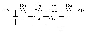
Because I expected junction temperature of power MOSFETs would vary with the amplified signal, I decided that the one-bend amplifier needed a more thorough SPICE simulation of the thermal design. Fortunately, I found that Vishay had published thermal models of their IRFP240 MOSFETs in a separate datasheet. Figure 1 below shows the model I chose to use of the two presented.| Figure
1:
Thermal
model
for
IRFP240
and
presumed
for
IRFP9240
as
well. |
 |
| RF1 | |
60.8721mΩ |
| CF1 | 1.5231mF | |
| RF2 | 125.9014mΩ | |
| CF2 | 6.5766mF | |
| RF3 | 295.8460mΩ | |
| CF3 | 11.5740mF | |
| RF4 | 347.3805mΩ | |
| CF4 | 103.6350mF |
Next I looked at heat sinks. One promoted for 0.1ºC/W with natural convection turned out instead to be for forced cooling instead. Therefore it would be underweight at 0.9kg for one using natural convection. As a result, I estimated a hypothetical weight for a natural convection heat sink to be a minimum of 6.4kg. Calculate thermal capacitance for this mass.
| (6) |
CθSA = specific heat × mass = | 0.9 |
J
ºC⋅kg |
× 6.4kg = 5.76 |
J
ºC |
Figure 2 below combines this heat sink data with that given for the MOSFETs.
| Figure
2:
Full
thermal
model |
 |
| Note: ZθJCx's represent entire MOSFET thermal model from figure 1 above |
For the actual SPICE model, I modeled the MOSFETs paralleled into groups of four by multiplying the capacitances and dividing the resistances each by four to produce a combined model for each parallel NMOS and PMOS bank.
| Figure 3: SPICE thermal model |
| * thermal circuit of 8 MOSFET
follower stage * set ambient temp v1th ta 0 dc 25 * calculate instantaneous power dissipation b1th 0 tjp i=abs((i(vpos2:x1))*(v(vdd2)-v(vout))) b2th 0 tjn i=abs((i(vneg2:x1))*(v(vout)-v(vss2))) * lumped model of positive NMOS bank xthpjc tjp tcp ta thirfp240_4 rthpcs tcp ts 60m * lumped model of negative PMOS bank xthnjc tjn tcn ta thirfp240_4 rthncs tcn ts 60m * heat sink model mass=6.4kg rthsa ts ta 0.1 cthsa ts ta 5.76 * individual transistor model included for reference .subckt thirfp240 tj tc ref rf1 tj t1 60.8721m cf1 tj ref 1.5231m rf2 t1 t2 125.9014m cf2 t1 ref 6.5766m rf3 t2 t3 295.8460m cf3 t2 ref 11.5740m rf4 t3 tc 347.3805m cf4 t3 ref 103.6350m .ends * lumped transistor model actually used .subckt thirfp240_4 tj tc ref rf1 tj t1 15.218m cf1 tj ref 6.0924m rf2 t1 t2 31.4753m cf2 t1 ref 26.3064m rf3 t2 t3 73.9615m cf3 t2 ref 46.296m rf4 t3 tc 86.8451m cf4 t3 ref 414.54m .ends |
The thermal model was included in the overall amplifier model and the following analyses were run.
SPICE amplifier model
SPICE thermal model
SPICE power supply model
Simulation results
| Figure 4: Operating point analysis. |
| ta = 25
tcn = 57.51615 tcp = 57.51632 tjn = 83.46631 tjp = 83.46706 ts = 50.01249 |
Figure 5: Transient analysis at zero output shows smooth rise to temperature.. |
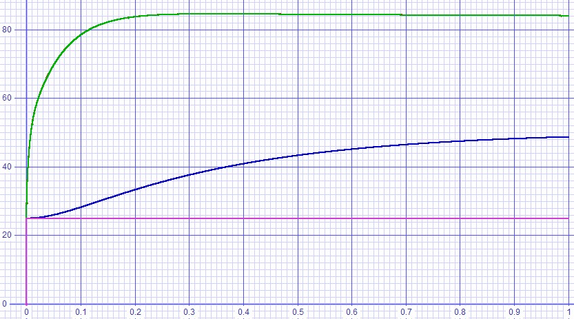 |
Figure 6: Transient analysis driving one watt into 8Ω. |
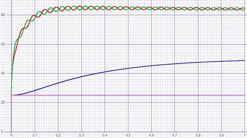 |
Figure 7: Transient analysis driving 30W into 8Ω. |
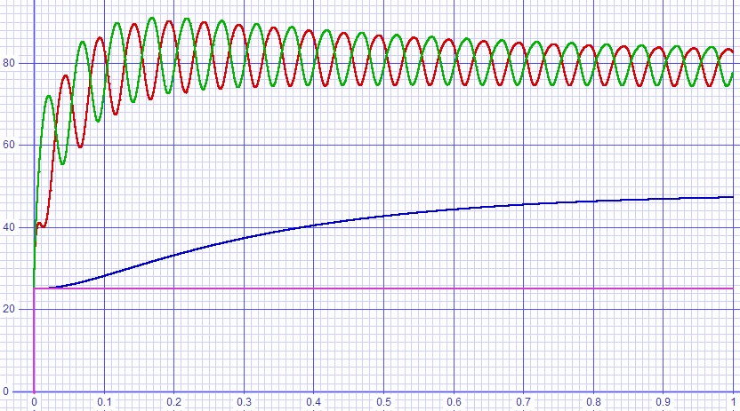 |
Figure 8: Transient analysis driving 60W into 4Ω. |
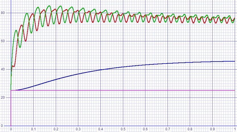 |
Comments on simulation
The results turned out well. Peak junction temperatures only reached 91ºC, only 7.5 degrees higher than the 83.5ºC operating point without an input signal. The 50ºC heat sink temperature that resulted was fortunate because that is about the highest temperature that you can hold with your hand without feeling that the metal will burn you. Perhaps it should have been a design objective as well in addition to junction temperatures well below the 150ºC maximum.|
|
Document History
August 17, 2013 Created.
November 27, 2015 Corrected some wording.
August 23, 2016 Restored missing subfile to SPICE model.