 |
| Home │ Audio
Home Page |
Copyright © 2009, 2010, 2011, and 2012. Free use of program governed by statement in About dialog which is repeated below.
Updated December 9, 2015. See Document History at end for details.
Phono Termination Calculations and Calculator
Introduction
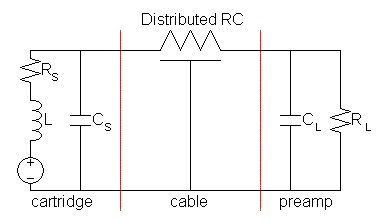
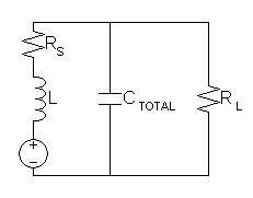
Desire to compute an accurate model of the LCR response of the phono input loop led to these calculations and calculator. Figure 1 represents what I believe an accurate model of this circuit. An assumption that the total cartridge and load resistance is of some magnitude greater than the series cable resistance (RS + RL >> RCABLE) allows adding capacitors in parallel to form the model of figure 2.
| Figure 1: phono input loop model |
|
|
| Figure 2: simplified model |
|
|
Calculations
Reduce equations
| (1) |
H(s) = |
|
= |
1
|
| (2) |
H(s) = | 1
|


| (3) |
H(s) = |
|
Equate denominator to standard form to show radian frequency and quality factor.
| (4) |
s2LC |
|
RL
RS + RL |
|
+ s |
|
L + RSRLC
RS + RL |
|
+ 1 = | s2
ω2 |
+ |
s
Qω |
+ 1 |
Calculate radian and normal frequency.
| (5) |
ω = |
|
, f = | ω
2π |
Solve for Q.
| (6) |
Qω = | RS
+ RL
L + RSRLC |
| (7) |
Q = | RS + RL
L + RSRLC |
|
= |
|
Derive frequency optimization from equation (5)
| (8) |
ω2 = | RS
+ RL
LCRL |
, therefore C = | RS
+ RL
ω2LRL |
From equation (7), begin to
derive C from Q and RL from Q optimizations:
| (9) |
QL + QRSRLC = | LCRL (RS + RL) |
| (10) |
Q2L2
+ 2Q2LRSRLC + Q2RS2RL2C2
= LCRL
(RS
+ RL) |
Solve for C from Q:
| (11) |
(Q2RS2RL2)C2 + (2Q2LRSRL - LRL(RS + RL))C + Q2L2 = 0 |
Since the solution for C is setup for a quadratic solution, specify coefficients and solve:
a2 = Q2RS2RL2
a1 = 2Q2LRSRL - LRL(RS + RL)
a0 = Q2L2
| C = |
2a2 |
This solution gives two roots where a single result is
expected. Programmatically, I decided to choose the correct root
by calculating Q back from equation (7)
for each.
Solve for RL from Q:
| (12) |
(Q2RS2C2 - LC)RL2 + (2Q2LRSC - LCRS)RL + Q2L2 = 0 |
| (13) |
(Q2RS2C2 - LC)RL2 + ((2Q2-1)LCRS)RL + Q2L2 = 0 |
a2 = Q2RS2C2 - LC
a1 = (2Q2-1)LCRS
a0 = Q2L2
| RL = |
2a2 |
This
solution gives two roots where a single result is
expected.
Programmatically, I decided choose the correct root by verifying the
results by calculating Q back from equation (7).
The full optimization is now iterated by alternately repeating the
optimizations specified under equations (8) and (13) until they
converge to a unified result. This optimization imposes no
boundary limitation on the program. A direct calculation would
require solving a pair of non-linear simultaneous equations, something
unnecessary for the moment.
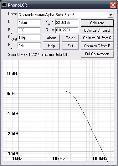
Calculator
Based on above calculations, I am offering a simple calculator for
download. It is
well tested in Windows XP and Windows 98. Modifications improving
portability enable operation under
Linux using Wine (Windows Emulator)1
as well.
|
|
EULA
I retain copyright. You may freely use it
for personal,
non-commercial, use (that is you cannot offer it for sale). You
may share
it with others as long as it is provided to them complete and
unmodified as you
get it from this website. After download, extract the contents of
the zip
file into the desired directory. You will have to manually create
links
on the desktop or the start menu, as you desire.
Download
 |
Download PhonoLCR.3.3.0.zip (Adds shortcuts for entry of Bessel and Butterworth Q values, 15KB) |
|
Download PhonoLCR.3.2.2.zip
(Adds mouse functions for graph inspection, 15KB) |
|
|
Download PhonoLCR.3.1.0.zip
(Adds bode plot,cartridge list and serial Q display, 14KB) |
|
|
Download PhonoLCR.3.0.0.zip
(Old version 3.0.0, with bode plot and cartridge list, 13KB) |
|
Download PhonoLCR.exe (Old
version 2.1.0, with bode plot, 40KB) |
Instructions
(These are to serve in place of a program help file)
Important notes:
- The serial Q, that which the
circuit exhibits with RL
omitted, determines the a fixed upper limit for the Q for the entire
parallel-series LCR circuit. (Obviously, L and RS are fixed
by the cartridge)
Because I forgot to anticipate this, attempts to optimize a higher Q
will result
in an error. The latest version of the program is produces an
error message which does not attribute the correct cause. A newly
added display of a running serial Q calculation show typical serial Q
values much higher than any reasonable total Q. It seems
sufficient to allow user discretion in choosing Q optimization goals
below the serial limit rather than alter the optimization routines to
detect violation of this
boundary.
- The iterative calculations of older versions (versions <= 2.0.1) of program have bounds, any inputs producing results that exceed these bounds will be limited to them, producing an error. The bounds currently are:
0Ω < RL < 1MΩ
1pF < CTOTAL < 1nF
- Attempts to use the calculator to calculate current input termination by setting RL near zero will produce meaningless results because the very low Q values that result give two separate first order poles, a low one calculated from L and RS and much higher one calculated from CTOTAL and RL. This is because, as Q drops, the two complex conjugate poles of higher Qs transform into separate real poles at Q = 0.5, then begin to diverge in frequency as Q is lowered further.
1. Basic Operation: Calculate frequency and Q from input parameters.
Obtain manufacturer's specifications for L, RS,
CS,
CCABLE, CL, and RL. Alternately,
you
can
measure
them
with
a
LCR
meter
(ones
that
measure
ESR
as
well
may
be
most
accurate)
after
disconnecting
cables.
Measure
cartridge,
cables,
and
preamp
input
separately.
It
is
difficult
to
measure
the
cartridge
capacitance
because
the
transducer
is
primarily
an
inductor.
You
can
estimate
it
to
25pF.
Total
all
capacitances.
Enter
data
into
program
and
press
Calculate. Data entry accepts standard
metric
prefixes without units, i.e. m, k, M, p, etc. Use u for micro.
Alternatively use the
Cartridge Name control by which
L and RS can be input from a
list of well known cartridges. I would still recommend measuring
these values with a LCR meter as specifications may vary. One
manufacturer even specifies L implausibly lower than the rest.
|
|
|
||||||||||||||||||||||||||||||||||||||||||||||||||||||
Note on cartridge measurements:
Cartridge electrical characteristics are affected
by the
mechanical loading on the stylus. This is because the mechanical
circuit
characteristics (mass, compliance, and damping) are reflected across
the
transducer interface as electrical parameters much the same as the
loading on
the primary of a transformer is reflected across to the
secondary.
Although this effect may be small, it is therefore desirable to measure
the
cartridge loaded in the closest manner to its loading during
playback.
The following three loading methods are presented in diminishing order
of
preference:
- Leave the cartridge in the tonearm but disconnect the connecting wires for measurement and disconnect power from the turntable motor. Then rest the needle in a groove of a scrap record. Perhaps the lead-out groove of a good record could be used (That last repeating groove that never gets played unless your turntable lacks automatic return). Then proceed with measurements.
- Do procedure (a) except rest the stylus directly on the platter mat.
- Hold the stylus stationary between your fingers while making the measurements.
2. Optimize from Q: Optimize loading (R or C) for a desired Alignment and Q.
After initial calculation, enter Q for alignment
chosen from
table below and press desired optimization button (Optimize C from Q or Optimize RL from Q) to
optimize.
The
optimized component will change value in its entry box. You
may want to choose the optimization that gives a higher capacitance or
a lower
resistance, as these only require an easier addition of a parallel
component. If setting a desired Q results in undesirable
high-frequency roll off, you may optimize for a higher frequency as in
next
instruction.
Q
Alignment Table (dB are
peak ripple)
|
Alignment |
Q |
Characteristics |
|
Bessel |
0.5773 |
Best transient response. More attenuation in passband before 3db cutoff than the others |
|
Butterworth |
0.7071 |
Flattest frequency response near 3db cutoff without any ripple (peaks). Transient response has some ringing. |
|
0.1dB Chebychev |
0.7674 |
All Chebychev alignments gain sharpest
cutoff in stopband at the expense of passband ripple and more transient
ringing. 0.1dB passband ripple (peak). |
|
0.25dB Chebychev |
0.8093 |
0.25dB passband ripple (peak). |
|
0.5dB Chebychev |
0.8637 |
0.5dB passband ripple (peak). |
|
1.0dB Chebychev |
0.9565 |
1dB passband ripple (peak). |
|
2.0dB Chebychev |
1.1286 |
2dB passband ripple (peak). |
|
3.0dB Chebychev |
1.3047 |
3dB passband ripple (peak). |
New as of version 3.3.0
The Q entry box has shortcuts for Bessel and Butterworth Q entry.
Entering an a or b into the first character of the Q entry will be
immediately replaced with a valid Q as follows:
| a |
|
Bessel |
| b |
Butterworth |
3. Optimize C from F: Optimize capacitive loading for a new frequency.
After initial calculations, enter new F value and press Optimize C from F. The optimized C will appear in its entry box. You should then follow with an Optimize RL from Q optimization as in step 2 above.
Note: Single optimizations will alter the unoptimized variable to
some extent, requiring further adjustments. Their use is
anticipated where the user is only willing to adjust one component to
optimize his results or where practical boundaries exist.
I.e. Hardware limits on minimum capacitance.
4. Full Optimization
Enter L, RS, F, and Q. Press Full
Optimization to optimize CTOTAL and RL from
input. Unlike the other options, there is no shift of an
unadjusted
parameter. Back calculation of F and Q from rounded values of CTOTAL
and RL for verification may result in a small amount of
round-off error.
5. Plot response
Now program shows bode (frequency response) plot as soon as a calculate or optimize button is pressed. If you want to see other plots (phase, etc...), obtain free FilterPro calculator from Texas Instruments www.ti.com. Enter values passband=Lowpass, Poles=2, Filtertype=CustomFn&Q, then desired Fn and Q in table in that order. Touch on any other input box without changing anything and the graph will respond.
6. Reset button
Pressing the Reset button
will restore default component values. Reset also reloads the cartridge
data file in case you desire to change it while the program is running.
7. Mouse functions
Mouse functions added in version 3.2.0 allow closer examination of
the graph.
- Left mouse button - Click at desired frequency point to show exact magnitude response at that point.
- Right mouse button - Click to show important values: the -3dB frequency and the magnitude at 20kHz.
- Display hold - If the mouse pointer is moved out of the graph with a button held down then released, the graph will hold the selected mouse function until a mouse click is made in the graph again. Useful to get a screen shot with Alt-PrtSc without simultaneous manipulations of the mouse.
8. Manual adjustments
In case measured or published specifications do not produce an
adequate result, manual adjustments to cartridge loading may be
necessary. If sound is too warm, Q or F is low. First try
lowering CL to raise F before raising RL to raise
Q. If sound is too bright, Q is high. Lower RL
to lower Q. If the warm/brightness balance is good but there
seems a lack in high-frequency extension, lower CL to
raise F. This calculator could assist in these manual adjustments
by showing the general trend of changes adjustments might make.
This calculator shows a general fault with setups of a low
resonant frequency, so it is better to err on the side of a low CL.
9. Additional Note
The data file phonolcr.txt
contains the cartridge data selected by
the Cartridge Name control and
user initialization for CTOTAL
and RL. Be sure it resides in the same
directory as
the program. The file contains instructions for adding new parts
or user initialization.
SPICE verification
Simulation of various lowpass LCR combinations produce the same
results as the program.
SPICE model.
A note on basic electronics:
Resistors in parallel and capacitors in series do not add directly but rather by the following formula:
| RPARALLEL = | 1
1/R1 + 1/R2 |
= |
R1R2
R1 + R2 |
, CSERIES = | 1
1/C1 + 1/C2 |
= |
C1C2
C1 + C2 |
Resistors in series and capacitors in parallel add directly:
RSERIES = R1 + R2, CPARALLEL = C1 + C2
Windows 95 may not have the shared Visual C++ 6.0
dlls
needed to run this program. If you have any problem that
implicates a
missing file, mfc42.dll or msvcrt.dll, download here,
and copy
into the directory with the program or into the windows system
directory
(c:\windows\system\ or c:\windows\system32\ whichever
contains
system dlls).
|
|
Download mfc42.dll (1004KB) |
|
|
Download msvcrt.dll (335KB) |
|
|
1Specifically, Wine
version 1.1.42 under Kubuntu 10.04 Lucid Lynx. You
will
have
to
copy
mfc42.dll
and/or
mfc42u.dll
to
~/.wine/drive_c/windows/system32
directory
for
proper
operation.
Document History
August 10, 2009 Created.
August 10, 2009 Revised.
September 18, 2010 Modifications
improving portability enable use under Linux with windows emulator.
October 2, 2010 Version 2.0 adds bode (frequency response) plot
to program.
October 3, 2010 Add note to instructions concerning boundaries
for
iterated calculations and expected errors for out of range inputs that
may cause them.
October 5, 2010 Version 2.0.1 verifies iterative calculations and
prints an error message if bounds exceeded.
October 12, 2010 Version 2.1.0 does direct calculations for all
single optimizations. Iteration of full optimization now
converges without boundaries. Show derivation of new
equations.
October 13, 2010 Added SPICE verification.
March 24, 2011 Added.pulldown combo control to program choosing
cartridge
and
loading its published L and RS specifications from a
user-editable text file.
March 24, 2011 New program file PhonoLCR.3.0.0.zip was corrupted,
uploaded again. If it failed for you, redownload it.
March 24, 2011 Improved program to
invalidate results of currently chosen cartridge when a new one is
chosen.
March 25, 2011 Improved program to handle accidental errors in
cartridge data file.
March 25, 2011 Improved program to allow user to define initial CTOTAL
and RL in cartridge data file.
April 29, 2011 Corrected a one word grammar error and simplified
a wordy phrase.
August 20, 2011 Added a note concerning the limitations imposed
on the circuit and program by its serial Q.
August 23, 2011 Added a running serial Q calculation display, and
a reset
button.
April 23, 2012 Added mouse functions for graph examination to new
program version 3.2.0. Documented at instruction 7.
April 23, 2012 Fixed program malfunction causing wrong -3dB right
mouse
button result for Q < 0.7071 raising program version to 3.2.1.
April 30, 2012 Raised program version to 3.2.2 incorporating
faster graph updates under mouse inspection.
September 13, 2012 Raised program version to
3.3.0 adding shortcuts for entry of Bessel and Butterworth Q values.
December 9, 2015 Improved formatting.