 |
| Home │ Audio
Home Page |
Copyright © 2011 by Wayne Stegall
Created January 26, 2011. See Document History at end for
details.
Flicker Noise Calculations
Introduction
As a result of expanding the functionality of the Op Amp Noise Calculator, I thought it useful
to do another article on noise.
For most noise calculations pertaining to electronics, it suffices
to consider white noise only. However account of another
type of noise does sometimes merit concern. That is flicker or
1/f noise. The power of this noise of unknown origin is inversely
proportional to the frequencies of interest, distributing equal power
to every octave. This pink noise profile declines 10dB/decade or
3dB/per octave, a rate half that of the stopband rolloff of a
first-order RC network. Added root-sum-square to the white noise
level also present creates a noise response break frequency below
which the flicker
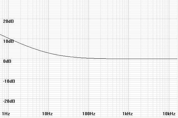
noise rises at its characteristic rate. This noise corner frequency is the
frequency where the flicker noise is equal to the white noise
specification in V/√Hz (see figure 1 below).
If you are new to noise calculations you may want to examine Simple Noise Calculations
before proceeding.
| Figure
1:
Noise
plot
shows
1/f
noise
rise
below
10Hz
noise
corner
from
normalized
white
noise
level |
 |
Mathematical Analysis
The specification of (f) or (f1,f2) next to power or voltage in these analyses indicate that these variables are functions of frequency or a range of frequencies and does not indicate a multiplication. Multiplication will be indicated by another level of parentheses or an ×.Because noise is always specified relative to frequency in Hz rather than radian frequency, it is well to derive the math based on f rather than ω.
The flicker power function (in W/Hz) is inversely proportional to the frequency.
| (1) |
pfn(f) = |
k
f |
Because the mean square voltage1 and current are proportional to their corresponding power, that is vn(f)2 = pn(f)R, then
| (2) |
vfn2(f)
= |
kR
f |
Because it is common to relate flicker noise to the characteristic white noise at a frequency where both are equal called the noise corner frequency (fnc),
if we set
| (3) |
k = | vwn2(f) × fnc
R |
the equation (2) becomes:
| (4) |
vfn2(f) = vwn2(f) | fnc
f |
vwn(f) here represents the semiconductor white noise specified V/√Hz in datasheets; vfn(f) is specified in units of V/√Hz as well.
Integrating the 1/f function through the range of frequencies representing bandwidth gives the corresponding total mean square flicker noise
| (5) |
vfn-total2(f1,f2) = | ∫ |
|
vwn2(f) | fnc
f |
df |
Knowing that ∫1/f df = loge(f) = ln(f) the integral becomes
| (6) |
vfn-total2(f1,f2) = vwn2(f) × fnc × (ln(f2)-ln(f1)) |
That subtraction of logarithms is equivalent to division allows a more convenient representation.
| (7) |
vfn-total2(f1,f2) = vwn2(f) × fnc × ln(f2/f1) |
Take the square root of total mean squared voltage noise to get total flicker noise:
| (8) |
vfn-total(f1,f2) = vwn(f) |
|
Adding It Up
After calculating flicker noise it is well to add up all noise sources. Flicker noise adds root-sum-square as does white noise.Total white noise specified as a function of voltage noise per √Hz and bandwidth is:
| (9) |
vwn-total(f1,f2) = vwn(f)√B = vwn(f) |
|
Square total white noise and flicker noise and add them to get total mean square noise:
| (10) |
vn-total2(f1,f2) = (vwn2(f) × (f2 - f1)) + (vwn2(f) × fnc × ln(f2/f1)) |
Take square root of total mean squared voltage noise to get total noise:
| (11) |
vn-total(f1,f2) = vwn(f) |
|
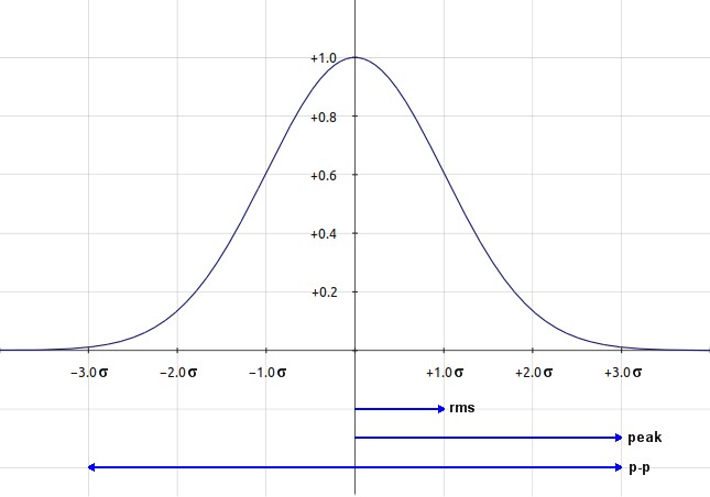
A Statistical Diversion
|
|
Reading Datasheets
Datasheets often give flicker data in a form other than the most useful noise corner frequency (fnc). A midband noise specification will be given for the white noise. A single specification at a lower frequency will contain flicker and white noise from which fnc can be calculated. Alternatively, a noise total for a range of frequencies below the white noise specification will be given.First, if necessary convert any peak-to-peak specifications to RMS by dividing by 6 (refer to note on conversions above), then calculate the noise corner frequency from equations (13) or (14) below.
Derive the formula for fnc based on a single low frequency specification.
First, solve the 1/f formula of equation (4) for fnc.
| (12) |
fnc = | vfn2(f) × f
vwn2(f) |
Substitute the subtraction of the square of the white noise specification from the total noise specification for the square of the flicker noise specification (all in V/√Hz) to yield the final formula.
| (13) |
fnc = | (vn-total2(f)
-
vwn2(f)) × f
vwn2(f) |
Derive the formula for fnc based on a noise total for a range of frequencies.
Solve equation (11) for fnc to get formula deriving fnc from a noise specification through a range of frequencies.
| (14) | fnc = | (vn-total(f1,f2)/vwn(f))2
+ f1 - f2
ln(f2/f1) |
Example
Take the following specifications from the LSK170 datasheet:- Midband white noise specification, vwn(f) = 0.9nV/√Hz at 1kHz
- Low-frequency noise specification, vn-total(f) = 2.5nV/√Hz at 10Hz (both are labeled en2)
From equation (9) calculate total white noise:
| vwn-total(f1,f2) = 0.9nV/√Hz |
|
= 0.9nV/√Hz |
|
From equation (13) calculate noise corner frequency.
| fnc = | ((2.5nV/√Hz)2- (0.9nV/√Hz)2)
×
10Hz
(0.9nV/√Hz)2 |
= | (6.25a(V2)/Hz - 0.81a(V2)/Hz)
×
10Hz
0.81a(V2)/Hz |
| fnc = | (5.44a(V)2/Hz) × 10Hz
0.81a(V)2/Hz |
= 6.71605 10Hz = 67.1605Hz |
From equation (8) calculate total flicker noise.
| vfn-total(f1,f2) = 0.9nV/√Hz |
|
= 0.9nV/√Hz |
|
| vfn-total(f1,f2) = 0.9nV/√Hz |
|
= 0.9nV/√Hz |
|
Calculate total noise from total white noise and total flicker noise by root-sum-square:
vn-total2(f1,f2) = (127.216nV)2 + (19.3851nV)2 = 16.1839f(V2) + 375.782a(V2) = 16.5597f(V2)
vn-total(f1,f2) = 128.684nV
Final Thoughts
The example above illustrates an important point. The 128.684nV total after adding flicker noise to the white noise total of 127.216nV is only an increase of 0.1dB. It is often safe to ignore flicker noise and calculate white noise only if the noise corner frequency is near the lower end of the band calculated.You can tinker with flicker noise calculations with the Op Amp Noise Calculator.
|
|
1Mean square values are squared
rms values.
2E is sometimes used to
represent the voltage variable rather
than v, derived from
voltage's original name,
electromotive force or emf. The reason may lie with
combination
electro-mechanical systems, where v
is in conflict for use as voltage
and velocity, one of which has to be changed. E is not used in
place of Volt as a unit however. V is the preferred variable for
electronics-only applications because e is also the base of the natural
exponential, a common function in electronics mathematics. The
similar appearance of en and en, at least in
quick reading, could create problems that that use of v for emf would
alleviate.
Document History
January 26, 2011 Created.
January 26, 2011 Changed (f1-f2) to (f1,f2) to better represent
dual function arguments and added an additional comment at the end.
January 26, 2011 Corrected a name discrepancy that made equations
(11) and (14) seem inconsistent.
January 27, 2011 Made minor improvements for clarity and grammar.