Copyright © 2014 by Wayne Stegall
Updated May 27, 2014. See Document History at end for details.
Differential Equalization
Differential
circuit
transformation
has
application
to
differential
RIAA equalization
Introduction
An equalized differential circuit is redundant: one side repeating the
components found on the other. The following transformation
allows many of those components to be shared.
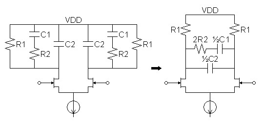
Concept
I
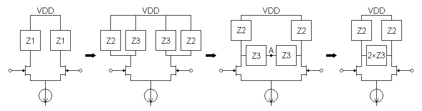
figure 1 following, if Z
1
can be subdivided into parallel components Z
2 and Z
3,
matching
parallel
legs of the circuit from each side can cross connect,
halving the number of components for that leg. The key to
understanding the transformation is to note that
node A where the two matching
parallel legs connect is a virtual ac ground. This is because the
circuit is topologically symmetrical with opposite polarity signals on
each side ensuring that the dc voltage component always remains
zero. Only the connection to another ac ground (V
DD in
this case) can be reconnected to make a virtual ground in this way.
Figure
1:
Schematic
shows step-by-step transformation of redundant
differential circuit to one with less components.
|
|
Derivation
The empirical derivation of the transformation seems reasonable
enough. However there are reasons not to accept it without
proof. For one thing, it is immediately obvious that transformed
circuit is not equivalent to the original for a single-ended
input. The impedance of the circuit seen by the output of one
transistor depends on the opposite polarity of ac signal being driven
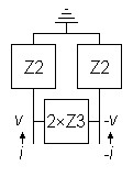
at the output of the second transistor. I deemed necessary to set
up an equation based on the principle of superposition: that is
to add the voltage contribution to the transistor ac output voltage of
each current together. Then it remains to solve for the
equivalent impedance.
Figure
2:
AC
schematic of transformed circuit
|
|
(1)
|
v = i(Z2 || (Z2
+ 2Z3)) – i
|

|
Z2
Z2 + 2Z3
|

|
(Z2 || (Z2
+ 2Z3)) |
(2)
|
Zequiv =
|
v
i
|
=
|
|
1 – |
Z2
Z2 + 2Z3
|
|
(Z2 || (Z2
+ 2Z3)) |
(3)
|
Zequiv =
|
|
2Z3
Z2 + 2Z3
|
|
|
Z2(Z2 + 2Z3)
Z2 + Z2
+ 2Z3 |
|
(4)
|
Zequiv = |
2Z3Z2
2Z2 + 2Z3
|
=
|
Z2Z3
Z2 + Z3 |
=
|
Z2 || Z3 |
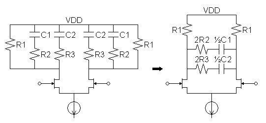
Examples
In practice, this transformation works best with equalization
topologies that have a parallel high level structure. For this
reason, the examples I give here meet such a requirement. The
actual calculation of component values in differential RIAA circuits
should use this article in conjunction with the calculations give for
single-ended circuits in the main RIAA equalization article.
1 Note also, as a
practical matter, that the main dc paths to V
DD have to
remain connected to V
DD and not combined into the cross
element.
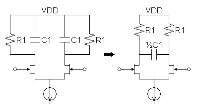
Transformation of parallel circuits
Figure
3:
Parallel
lowpass filter.
|
|
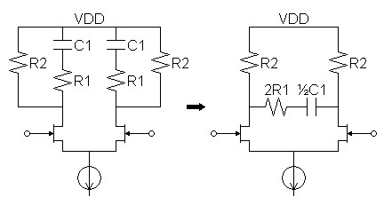
| Figure
4:
Parallel-series
shelf equalization circuit commonly used for
first stage of two-stage RIAA equalization. |
|
| Figure
5:
Parallel-series
(or passive) RIAA equalization circuit. |
|
| Figure
5:
Parallel-series
(or
passive) RIAA equalization
circuit with extra 50kHz zero. |
|
Transformation of partially parallel serial circuits
To be added later.
1See article: Phono Equalization Calculations.
Document History
May 27, 2014 Created.
May 27, 2014 Added a sentence and corrected some spelling.
