 |
| Home │ Audio
Home Page |
Copyright © 2010 Wayne Stegall
Updated November 27, 2010. See Document History at end for
details.
SPICE verified.
Cascode
Selector
Introduction |
Figure
1:
CMOS
Bilateral
switch |
| Semiconductor switches sometimes used as selectors in stereo equipment are regarded with suspicion by some because the FET's used are expected to add distortion to the signal. Common CMOS bilateral switches that allow logic control of analog signals are specified with an on resistance of 80Ω. The represents 12.5mS of nonlinear FET transconductance in its linear operating region which might be mitigated regarding distortion by increasing the load resistance on the output of the switch. If the p-channel and n-channel devices connected in parallel are matched, the resulting symmetrical transfer curve might produce a distortion result euphonic in the way push-pull class-a amplifiers are. | 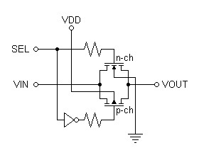 |
A Better Alternative
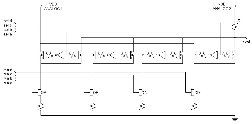
It is desireable to design to a transistor's strengths rather than to its weaknesses. A common transistor strength is the near perfect current output of its drain or collector. Here cascode FET's, two per line, switch the output current of multiple class-a biased transistors into either the output load or a supply voltage. The deselected FET would be out of the circuit due to high impedance and the selected FET would benefit the high-frequency response of the resulting class-a amplifier in the manner normally expected of a cascode. Here deselected signals are switched to supply voltage rather than being turned off completely because of risk of creating anomalies at the input by saturating the amplifying transistor. The result is a selector fit for class-a audio tastes. CD4000 series logic is needed to control the selector because only its range of supply voltages (5V-18V) are likely to provide an appropriate cascode gate bias. I do not show the amplifier input bias in the first schematic for the sake of simplicity. Any class-a design you desire with BJT, JFET, or MOSFET devices will interface with the selector in the same way. You can certainly try the bias and transistor choices of the SPICE example if you like. I show separate analog power supplies in the schematic below because decoupling deselected signal currents from the output circuit would benefit rejecting crosstalk between lines.| Figure
2:
Four-input
Cascode
Selector |
 |
Spice Simulation
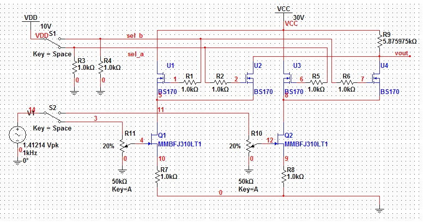
Because of the difficulty of modeling logic circuits in SPICE, I modeled a two-input cascode selector. The select logic can then be implemented with switches. This particular example does not have the lowest of distortion results. However, the class-a design is independent of the selector operation and can be improved. Here input trimmers lower the input signal to reduce distortion in the self-biased circuit before a gain of 5 restores the level. The trimmers were set for an overall gain of one to normalize the analysis of deselected channel rejection. The SPICE version used here is the Analog Devices trial version of MultiSim.
| Figure
3:
Schematic
Capture
of
Two-input
Cascode
Selector
for
SPICE
Analysis |
 |
| SPICE Model for circuit
of Figure 3. Figure 4: AC analysis of selected line shows selected signal at output |
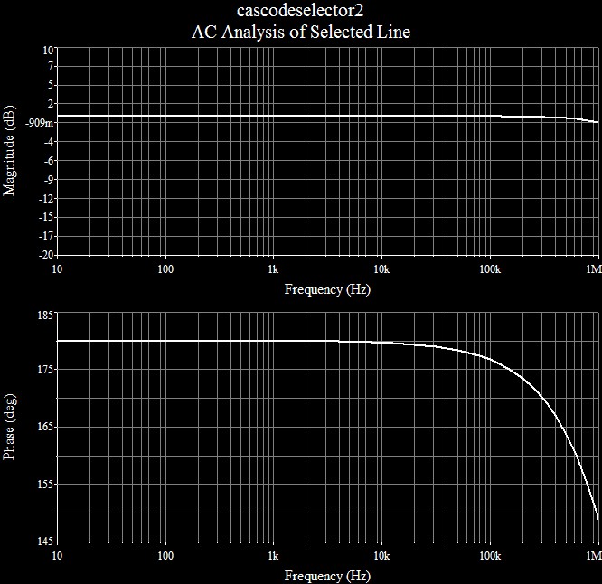 |
Figure 5: AC analysis of deselected line shows rejection of deselected signal at output. Reduction of rejection with frequency above 100Hz is due to FET drain capacitance. The result is still excellent overall. |
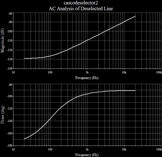 |
Figure 6: Fourier analysis shows euphonic level of second harmonic. |
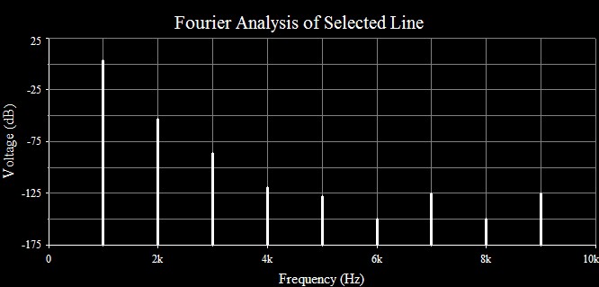 |
Figure 7: Second harmonic plot |
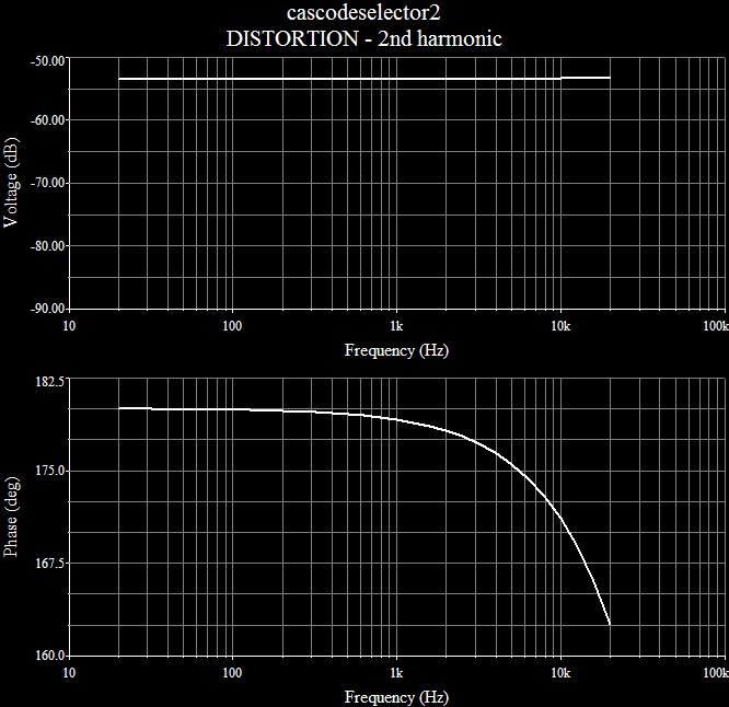 |
Figure 8: Third harmonic plot |
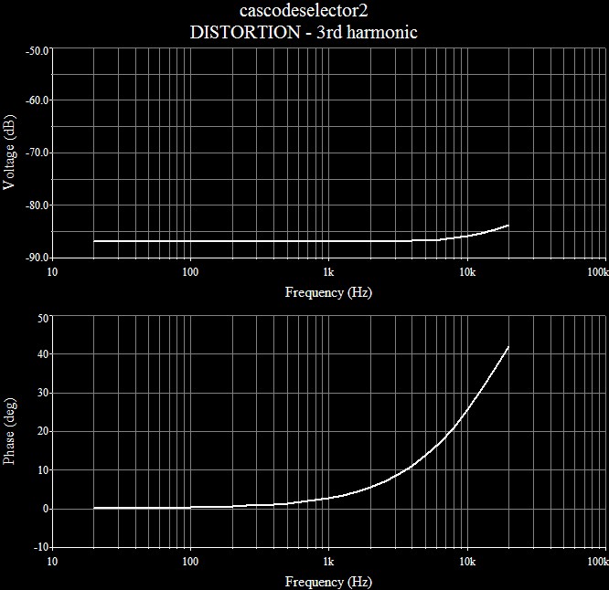 |
Figure 9: Fourier Analysis for Cascode Only (current signal driving source of BS170). Distortion -120dB and lower is below that of any amplifier circuit you might switch with it. |
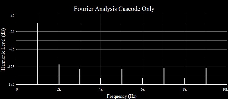 |
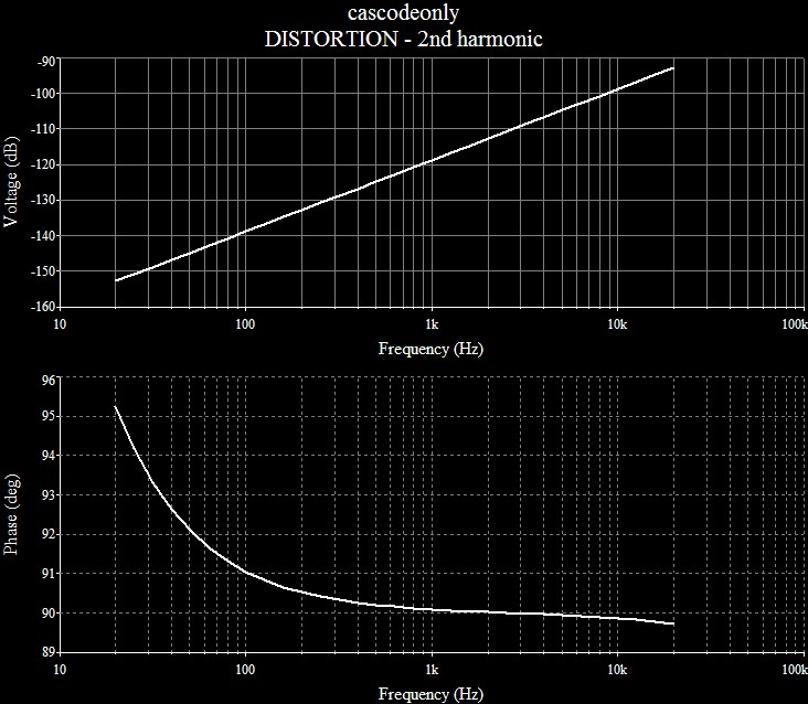
Figure 10: Second Harmonic Plot for Cascode Only. Third harmonic plot also has first order upward slope (20dB/decade). |
 |
Pushbutton Logic for Above Selector
Asynchronous logic control is desired for this circuit for several reasons. They do not broadcast radio frequencies (RF) and nor inject clock noise into the controlled circuit as synchronous logic or a microprocessor could. At most, a single RF click might come through when a new selection is made and no more. The logic circuit presented selects the output line activated by a momentary pushbutton switch and holds the output value after the switch is released. This functionality requires feedback to hold the selected value. Here NOR logic dictates the selected NOR gate have all zero inputs to produce the one output. When the selected switch is pressed, the input, normally zero by a pull down resistor, transmits a one to each deselected NOR forcing their outputs to zero. In this condition, feedback from the deselected zero outputs to the selected NOR together with zero inputs to that same NOR raise the output of the selected NOR to one, a condition that will remain until another line is selected. This circuit could be considered a multivariable set/reset flip-flop, indeed a two-line selector would only require a common SR flip-flop. Be sure to choose a digital supply voltage correct for the desired ON gate bias of the cascode.Table 1: OR/NOR Logic Table
| input |
output OR |
output NOR |
| all zeros |
0 |
1 |
| any ones |
1 |
0 |
Circuit
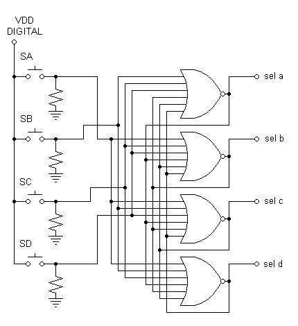
| Figure 11: Schematic of Push-button Logic for Four-input Cascode Selector |
 |
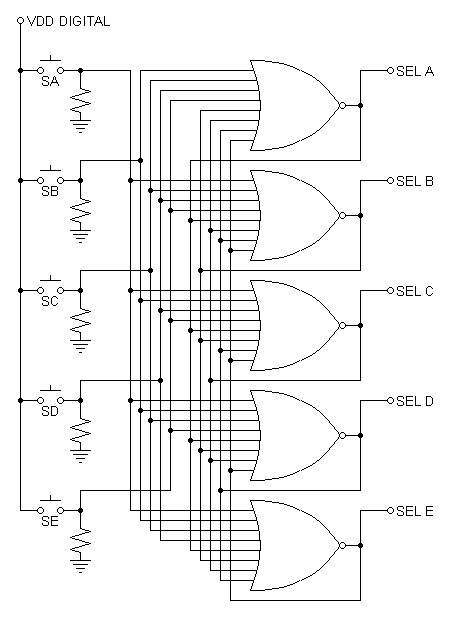
| For n lines, n NOR gates with
2(n-1) inputs each are required. Thus the use of 8-input NOR gates will only support 5 lines. Figure 12: Schematic of Push-button Logic for Five-input Cascode Selector. If you can deduce how both of these controls operate, how they are the same, and how they are different, you will be able to design one with a different number of signal lines. |
 |
If NOR gates larger than those available on standard ICs are required, they may be built up by connecting OR gates to the inputs of the largest NOR gate available. This is because the OR boolean function is associative and commutative as addition is in normal math. Figure 13: Ten-input NOR Constructed from 3-input OR and 8-input NOR. A controller for a six-line selector would require this gate. Boolean function equivalent: k = NOT((a OR b OR c) OR d OR e OR f OR g OR h OR i OR j) |
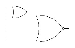 |
Table 2: Gates Useful to Selector Construction
| Part Name |
Part Description |
Appears in this article |
| CD4001 |
Quad 2 input NOR gate |
|
| CD4002 |
Dual 4 input NOR gate |
|
| CD4078 |
Single 8 input OR/NOR gate |
yes |
| CD4075 |
Triple 3-input OR gate |
yes |
| CD4049 |
Hex inverter |
yes |
Note: Gate inputs in the CD4000 logic family are limited to 2, 3, 4, and 8 in number. Any unused inputs on used or unused gates should be tied to logic 0 or 1 as follows:
OR/NOR: Tie unused inputs to logic 0.
AND/NAND: Tie unused inputs to logic 1.
Verification of Pushbutton Logic
I decided to verify the above logic circuit with a C program rather than SPICE. (Only verified with gcc compiler for now.)
| Figure
14:
C
Code
Verifying
Pushbutton
Logic |
| /* pushbutton.c Simulate pushbutton logic circuit */ #include <stdio.h> #define LINES 4 void main(void) { int in[LINES],out[LINES],tmp[LINES]; int ch,h,i,j; printf("\n\nInstructions:\n" \ "input a up to simulate activation of normally open pushbutton.\n" \ "input q to quit.\n" \ "input any other letter to simulate steady state retention of last.\n" \ " selected input"); printf("\n\nlines "); for(i=0;i<LINES;i++) printf("\t%c",'a'+i); printf("\n\n"); do { /* initialize inputs to 0 */ for(i=0;i<LINES;i++) in[i] = 0; printf("Enter line to active or q to quit: "); ch = getchar(); /* guard for the return character getchar was capturing on the subsequent pass after every input */ if(ch == '\n') ch = getchar(); ch = tolower(ch); if(ch >= 'a' && ch <= ('a'+LINES-1)) in[ch-'a'] = 1; printf("\n\nlines "); for(i=0;i<LINES;i++) printf("\t%c",'a'+i); /* print inputs */ printf("\ninput "); for(i=0;i<LINES;i++) printf("\t%d",in[i]); /* calculate outputs twice to allow feedback to raise selected line */ for(h=0;h<2;h++) { for(i=0;i<LINES;i++) { /* initialize OR gate */ tmp[i] = 0; /* OR inputs of other lines only */ for(j=0;j<LINES;j++) if(j != i && in[j]) tmp[i] = 1; /* OR outputs of other lines only */ for(j=0;j<LINES;j++) if(j != i && out[j]) tmp[i] = 1; } for(i=0;i<LINES;i++) out[i] = tmp[i]?0:1; } /* print result */ printf("\noutput "); for(i=0;i<LINES;i++) printf("\t%d",out[i]); printf("\n\n"); } while (ch != 'q'); } |
Power Supply Recommendations
Maintaining the logic selection while ac power is off is a primary design goal. Also all connected CMOS must power up and down together to prevent unwanted side effects.Although the analog power supply design is out of the scope of this article because they are part of the class-a amplifier design, I refer you to redesign that in the article Line Level Class A Power Supply for this application.
As for the logic power supply, my first impression is that the CMOS logic will draw minimal current when idle and a mild spike on making a new selection. For VDD of 10V, the CD4078B datasheet rates a 10nA typical and a 500nA maximum quiescent current and a maximum output current of 2.6mA. With a worst case 500nA idle current consumption, a 9V battery would be a fine digital power supply. The datasheet of the Energizer 522 9V battery shows charge capacity declining with increasing current load. At the lowest rated current load of 25mA the battery is rated for 600mAh. Calculate battery life for 5 NOR gates drawing 500nA each:
| TBATTERY-LIFE = |
QBATTERY
IDEVICE × #CD4078B devices |
= |
600mAh
500nA × 5 |
= 240,000 hours = 27.38
years |
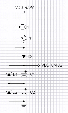
For those who want a power supply without a battery, one using supercapacitors will hold backup voltage for a long time. The series-parallel zener-capacitor topology below is required because of a 5.5V voltage limit on most supercapacitors. If you need more than 10V drive to cascode selector inputs you will need to expand the circuit with more zeners and capacitors. VDD-RAW input could be supplied by any other power supply in the system because the JFET current source provides significant line isolation. The bias through the zeners must be as much as the peak current drawn by two of the NOR gates plus the value of the minimum zener turn on current, because only two NORs change state on each new selection. Therefore IZ ≥ 2 × INOR-PEAK + IZB = 2 × 2.6mA + 1mA = 6.2mA. IZ ≥ 7mA would allow some extra margin of operation.
| Figure
15:
Supercapacitor
power
supply |
|||||||||||||||||||||||||
 |
|
Spice Results
| Figure
16:
Supercapacitor
power
supply
-
Line
rejection
shows
86.5dB
PSRR. |
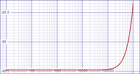 |
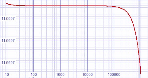
Figure 17: Supercapacitor power supply - Output impedance |
 |
SPICE Model for Supercapacitor power supply. |
Miscellaneous
LED selection indicators are desirable, yet direct CMOS drive would deplete the backup power supply. Therefore, I recommend a discrete MOSFET circuit. The MOSFET inputs will not draw any idle current and the supply to their drains through the LEDs and their bias can switch on and off with the main circuit without any effect. Small LEDs typically draw a maximum of 20mA. RiBIAS should set a bias limit of 10mA and RiADJ should adjust the bias down from there.| Figure
18:
LED
Selection
Indicator |
|
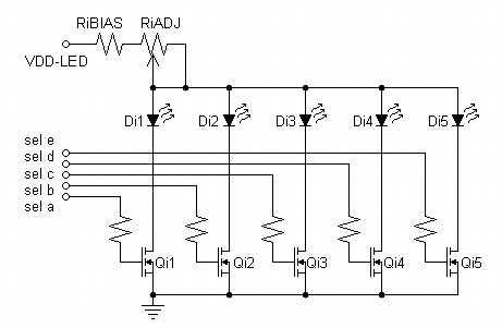 |
| RiBIAS = |
VDD-LED - VF-LED
ILED |
| RiBIAS = |
30V - 2.2V
10mA |
= 2780Ω |
Many would try different values from their parts supply and substitute a fixed value giving the desired brightness for RiBIAS and RiADJ.
Others might just use a two-pole six-position rotary switch as a selector in place of all of this! ;)
|
|
Document History
November 17, 2010 Created.
November 17, 2010 Made minor improvements.
November 18, 2010 Added a schematic for pushbutton logic to
control a
five-line selector and another demostrating how to build up larger than
standard NOR gates (for larger selectors) from smaller standard parts.
November 27, 2010 Added power supply recommendations and
a schematic for an LED indicator.