 |
| Home │ Audio
Home Page |
Copyright © 2013 by Wayne Stegall
Updated October 26, 2013. See Document History at end for
details.
Voice Control
Circuit enables
adjustable euphonic control
Introduction
An euphonic distortion result seems to be an important goal of high end audio. I understand that purists say that the euphony is a only pleasing side effect of the pursuit of a purity of sound that simple circuits create. However, some good results have been reported by adding an euphonic component to an otherwise undesirable neutral system. Here I assert that, with the proper circuit, adjustable euphony can be added to a system.Circuit
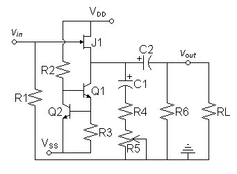
The circuit of figure 1 below
aims
to
meet
the
specified
goal.
A
square-law
or
near
square-law
buffer
is chosen for the basis because of near unity gain
under most circumstances. Then adjustable loading is provided by R4
and R5 through C1. This allows variation of
the magnitude of the output signal current relative to the bias.
Coupling through C1 ensures that the adjustment made does
not change the bias of the buffer itself. Since distortion is
proportional to the ratio of the signal to the bias, the amount of
distortion can be adjusted with potentiometer R5.| Figure
1:
Source
follower buffer with adjustable distortion mechanism |
 |
Initial Design
- Choose ±15V power supplies.
- R1 and RL chosen arbitrarily to standard audio load of 47kΩ.
- J1 chosen to be 2N3819 because of reasonably low noise and transconductance suitable for adjustment with reasonable values of R4 and R5. I presumed that a high transconductance transistor such as the LSK170 would require much lower values of load resistance for distortion adjustment.
- Decided to bias J1 to 5mA. Calculate R3 and R2 to create 5mA NPN current source.
|
(1)
|
R3 = |
VT-Q2
ID-J1 |
= |
0.7V
5mA |
= 140Ω |
Round to nearest 5% value:
R3 = 150Ω
R2 of 30kΩ would give somewhat less than 1mA of bias to Q2, choose 27kΩ for a little more.
R2 = 27kΩ
R3 = 150Ω
R2 of 30kΩ would give somewhat less than 1mA of bias to Q2, choose 27kΩ for a little more.
R2 = 27kΩ
- R6 chosen to have negligible effect on adjustment circuit.
R6 = 1MΩ
- Choose reasonable values for R4 and R5 to be adjusted during SPICE analysis.
R4 = 1kΩ
R5 = 100kΩ
R5 = 100kΩ
- Calculate C1 for a pole of 0.1Hz with respect to R4
|
(2)
|
C1 = |
1
2πfpoleR4 |
= |
1
2π × 0.1Hz × 1kΩ |
= 1.59155mF |
Round up to nearest 10% value:
C1 = 1.8mF
C1 = 1.8mF
- Although RL was presumed 47k initially, presume 10k instead for calculating C2.
|
(3)
|
C2 = |
1
2πfpoleRL |
= |
1
2π × 0.1Hz × 10kΩ |
= 159.155µF |
Round up to nearest 10% value:
C2 = 180µF
C2 = 180µF
SPICE Analysis
| Figure
2:
Initial
SPICE deck |
| * source follower buffer vpos vdd 0 dc 15V vneg vss 0 dc -15V v1 vin 0 dc 7 ac 1 sin 0 1.41421V 1kHz r1 vin 0 47k j1 vdd vin vsj1 2n3819 r2 vdd vbq1 27k q1 vsj1 vbq1 veq1 2n3904 r3 veq1 vss 150 q2 vbq1 veq1 vss 2n3904 c1 vsj1 vc1r4 1.8m * r4 sets maximum distortion limit r4 vc1r4 vr4r5 1k * adjust r5 from 0.1 to 100k (zero value resistances may cause simulation problems) r5 vr4r5 0 100k c2 vsj1 vout 180u r6 vout 0 1meg rl vout 0 47k .MODEL 2N3819 NJF( VTO=-2.9985 BETA=1.3046M LAMBDA=2.2507M RD=1 RS=1 + CGD=1.5964P CGS=2.4199P PB=500M IS=33.582F + BETATCE=-500M KF=0 AF=1 ) .model 2N3904 NPN (Is=6.734f Xti=3 Eg=1.11 Vaf=74.03 Bf=416.4 Ne=1.259 + Ise=6.734f Ikf=66.78m Xtb=1.5 Br=.7371 Nc=2 Isc=0 Ikr=0 Rc=1 + Cjc=3.638p Mjc=.3085 Vjc=.75 Fc=.5 Cje=4.493p Mje=.2593 Vje=.75 + Tr=239.5n Tf=301.2p Itf=.4 Vtf=4 Xtf=2 Rb=10) .end .control * transient analysis for 1k fourier tran 1u 0.1 0 1u uic fourier 1k vout .endc |
Initially I wanted a maximum distortion adjustment of ≥ 1%. My initial chosen value of 1k for R4 did not meet that specification. A subsequent attempt with 470Ω produced the following distortion result:
Fourier analysis for vout with R4 set at 470Ω R5 set to 0.1Ω:
No. Harmonics: 10, THD: 1.21397 %, Gridsize: 200, Interpolation Degree: 1
| Harmonic | |
Frequency | |
Magnitude | |
Norm.Mag | |
Percent | |
Decibels |
|
|
|
|
|
|
|
|||||
| 1 | 1000 | 1.02541 | 1 | 100 | 0 | |||||
| 2 | 2000 | 0.0124213 | 0.0121135 | 1.21135 | -38.3346 | |||||
| 3 | 3000 | 0.00081424 | 0.000794063 | 0.0794063 | -62.0029 | |||||
| 4 | 4000 | 6.98048E-05 | 6.80751E-05 | 0.00680751 | -83.34023 | |||||
| 5 | 5000 | 1.51983E-05 | 1.48217E-05 | 0.00148217 | -96.5820 | |||||
| 6 | 6000 | 7.35443E-06 | 7.17219E-06 | 0.000717219 | -102.887 | |||||
| 7 | 7000 | 6.4829E-06 | 6.32226E-06 | 0.000632226 | -103.983 | |||||
| 8 | 8000 | 5.73999E-06 | 5.59776E-06 | 0.000559776 | -105.04 | |||||
| 9 | 9000 | 5.25766E-06 | 5.12738E-06 | 0.000512738 | -105.802 |
Now to test my initial presumption of a 100kΩ maximum for R5.
Fourier analysis for vout with with R4 set at 470Ω R5 set to 100kΩ:
No. Harmonics: 10, THD: 0.00232116 %, Gridsize: 200, Interpolation Degree: 1
| Harmonic | |
Frequency | |
Magnitude | |
Norm.Mag | |
Percent | |
Decibels |
|
|
|
|
|
|
|
|||||
| 1 | 1000 | 1.40225 | 1 | 100 | 0 | |||||
| 2 | 2000 | 0.000022202 | 1.58332E-05 | 0.00158332 | -96.0086 | |||||
| 3 | 3000 | 1.47504E-05 | 1.05192E-05 | 0.00105192 | -99.5603 | |||||
| 4 | 4000 | 1.09449E-05 | 7.80524E-06 | 0.000780524 | -102.152 | |||||
| 5 | 5000 | 8.92295E-06 | 6.36333E-06 | 0.000636333 | -103.93 | |||||
| 6 | 6000 | 7.22369E-06 | 5.15151E-06 | 0.000515151 | -105.761 | |||||
| 7 | 7000 | 6.53083E-06 | 4.65741E-06 | 0.000465741 | -106.637 | |||||
| 8 | 8000 | 5.36301E-06 | 3.82458E-06 | 0.000382458 | -108.348 | |||||
| 9 | 9000 | 5.08764E-06 | 3.62821E-06 | 0.000362821 | -108.806 |
This load produces so little distortion that a value of 100k for R5 may not give any reasonable distortion adjustment range. Therefore try a value of R5 ten times that of of R4, that is 4.7k.
Fourier analysis for vout with R5 set at 4.7kΩ:
No. Harmonics: 10, THD: 0.0273854 %, Gridsize: 200, Interpolation Degree: 1
| Harmonic | |
Frequency | |
Magnitude | |
Norm.Mag | |
Percent | |
Decibels |
|
|
|
|
|
|
|
|||||
| 1 | 1000 | 1.35389 | 1 | 100 | 0 | |||||
| 2 | 2000 | 0.00036985 | 0.000273176 | 0.0273176 | -71.2711 | |||||
| 3 | 3000 | 1.92095E-05 | 1.41884E-05 | 0.00141884 | -96.9613 | |||||
| 4 | 4000 | 1.05354E-05 | 7.7816E-06 | 0.00077816 | -102.179 | |||||
| 5 | 5000 | 8.04703E-06 | 5.94364E-06 | 0.000594364 | -104.519 | |||||
| 6 | 6000 | 7.00937E-06 | 5.17721E-06 | 0.000517721 | -105.718 | |||||
| 7 | 7000 | 6.25483E-06 | 4.6199E-06 | 0.00046199 | -106.707 | |||||
| 8 | 8000 | 4.83021E-06 | 3.56765E-06 | 0.000356765 | -108.952 | |||||
| 9 | 9000 | 4.8342E-06 | 3.5706E-06 | 0.00035706 | -108.945 |
This minimum distortion result is still in the range considered to be inaudible. Because it is not a vanishing distortion result, choosing a potentiometer value near 4.7kΩ should give adequate adjustment range.
Design Changes
- Alter R4 and R5 to new values preferred in SPICE simulation.
R4 = 470Ω
R5 = 4.7kΩ
R5 = 4.7kΩ
- Now C1 must be recalculated because R4 was altered.
|
(4)
|
C1 = |
1
2πfpoleR4 |
= |
1
2π × 0.1Hz × 470Ω |
= 3.38628mF |
Round up to nearest 10% value:
C1 = 3.9mF
C1 = 3.9mF
Final SPICE deck.
Final parts list
| J1 |
|
2N3819 |
|
C1 |
|
3.9mF |
| Q1, Q2 |
2N3904 |
R4 |
470Ω | |||
| R1 |
47kΩ | R5 |
5kΩ potentiometer (with log taper?) |
|||
| R2 |
27kΩ | C2 |
180µF | |||
| R3 |
150Ω | R6 |
1MΩ |
Application Notes
The circuit is presented in its minimal form. Therefore the following notes may help in actual application.- Any square-law device could be used in the position of J1.
A
JFET
was
chosen
because of convenience: small-signal MOSFETs are
static sensitive and vacuum tubes have additional design requirements.
- In some cases the input should be capacitively coupled.
- An unloaded buffer could be added to the output to prevent
changing the effect with loading.
- The circuit could be used as a separate component installed in a
system to add the desired effect. Someone unfamiliar with euphony
could experiment with the idea himself.
- The circuit could be made into a unity-gain preamp by adding input switching and a volume control.
- Just the loading components could be added to the source-follower or cathode-follower of an existing circuit to add control of the voice to a component.
|
|
Document History
October 26, 2013 Created.
October 26, 2013 Improved formatting of Fourier analysis
results. Correct head calculation of R2 to 27kΩ.