 |
| Home │ Audio
Home Page |
Copyright © 2015 by Wayne Stegall
Updated November 14, 2015. See Document History at end for
details.
Turntable Geometry
Introduction
Vinyl records you play are cut on a machine where the cutter is always lined up with direction of the playing groove. Ideally a record should be played back the same way. However, the great majority of turntables play with a pivoted tonearm, one where the angle to the groove changes with the playing radius. Any error of this type adds distortion that a linear tracking tonearm does not introduce. Because of this, turntables with pivoting tonearms must be set up for minimum angle-induced distortion in order to play correctly.Some Theory
| Figure
1:
Diagram
illustrating
turntable
geometry |
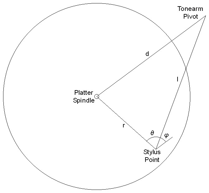 |
Refer to figure 1 above. Analysis of turntable geometry begins with the concern that the stylus be inline to the record groove to be played. However with a pivoting tonearm it is necessary to tolerate some angle error between the stylus and the groove. Then the task would be to align the cartridge to minimize this error for the range of radii in which playable grooves lie. Then high school trigonometry reminds us of the law of cosines as the first formula relating distances in the triangle between the stylus point, platter spindle, and the tonearm pivot to the angle indicated in figure 1 as θ.
| (1) |
d2 = r2 + l2 – 2rl·cosθ |
However θ is only related to the angle we desire. Substituting the sine of the complementary angle φ for the cosine of θ gives a related formula more suited to the task.
| (2) |
d2 = r2 + l2 – 2rl·sinφ |
Now the formula can be rearranged to solve for the angle of interest.
| (3) |
φ
= arcsin |
r2 + l2 – d2
2rl |
Then values of l and d are calculated which give a minimum variation in φ. Usually one value is fixed by the design of the tonearm and the other is calculated from it by means not necessary to detail now. Then if the cartridge is turned toward the spindle by the median value of φ through its range called the offset angle (φoffset) only a lesser error angle called tracking error with equal magnitude minimums and maximums remains.
| (4) |
φerr
= arcsin |
r2 + l2 – d2
2rl |
– φoffset |
| Figure
2:
Typical
plot
of
φ
optimized
for
minimum
angle
range.
(equation
3) |
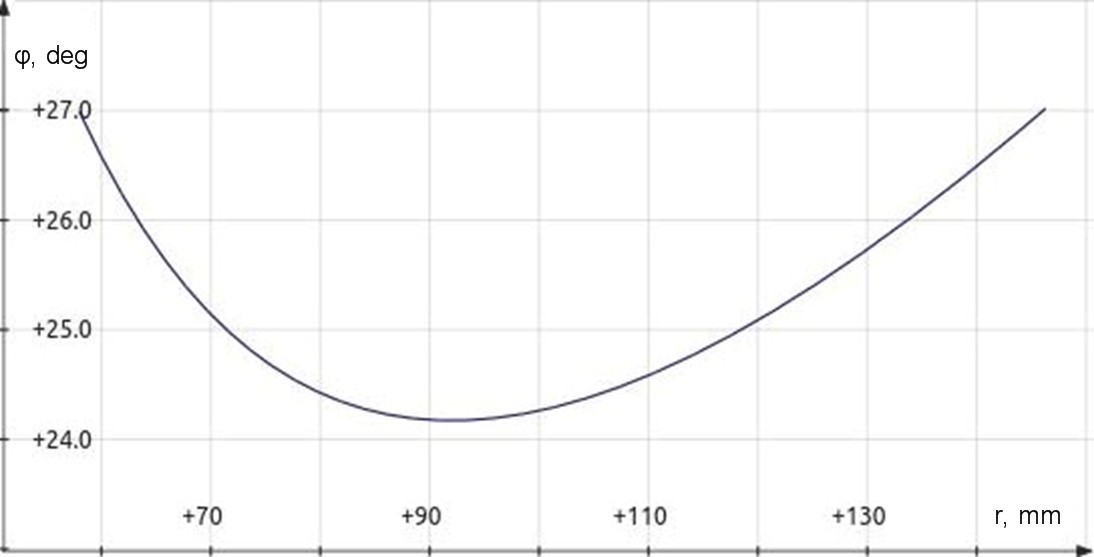 |
Figure 3: Typical plot of tracking error angle after stylus has been rotated by offset angle. (equation 4) |
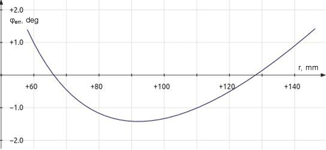 |
Although it seemed sufficient to minimize tracking error for a time, it was later determined that distortion was not determined by tracking error angle alone. It was further determined that distortion for any given angle error was also inversely proportional to the radius.
| (5) |
distortion ∝ | φerr
radius |
Therefore minimizing φerr/r became the new criterion for determining the correct tonearm setup.
| (6) |
distortion ∝ | φerr
radius |
= |
r |
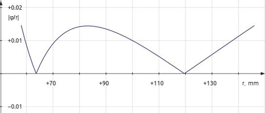
Once the correct geometry variables have been calculated, you see from figure 5 below that optimal calculations result in all maximum values being the same. Then radii at two zero crossings become the main focus for correct alignment as they represent the only points where the stylus is perfectly inline with the groove of the record.
| Figure 4: Plot of φ/r optimized for minimum distortion range resembles tracking error plot except that zero crossings are closer to spindle. (equation 6) |
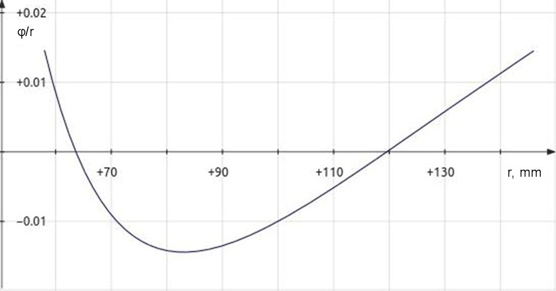 |
Figure 5: Plot of |φ/r| for optimized setup shows equal distortion maximums. |
 |
Note
Although not necessary for the context of this article, another figure of merit to optimized turntable geometry is overhang. Overhang is the difference between the effective arm length l and the pivot-to-spindle distance d. It is often given in place of pivot-to-spindle distance along with effect arm length in turntable specifications.| (7) |
overhang = l - d |
| (8) | d = l - overhang |
The use of overhang as a specification suggests aligning a cartridge by bringing the tonearm to the spindle until the stylus is in line with both the pivot and spindle and setting overhang as distance from spindle to stylus along with an offset angle presumed parallel to the lines of the headshell. Some early turntables specify a setup similar to this and produce results incorrect compared to more modern calculations and methods.
Software
I provide here a turntable geometry calculator oriented toward
minimizing |φ/r|.| Figure 6: Turntable geometry calculator |
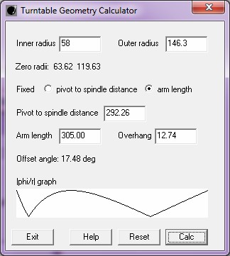 |
To get the new version 1.1.0 of the program with the |φerr/r| graph, download here.
The old version 1.0.0 of the program without the |φerr/r| graph is still available here.
Operation
- All numbers specified must be in the same units. The
default values given for inner and outer radii are in millimeters for
12 inch LPs. If you want to use inches or want to specify radii
for 45 records, you have to supply other values.
- The calculation of zero radii from inner and outer (minimum and maximum) radius is required for all calculations, others are optional.
- Choose which aspect of the tonearm adjustment is fixed: pivot to spindle distance or arm length.
- It is then best to then specify the fixed parameter then press calc.
- Sometimes tonearm specifications specify the two calculated values instead of the fixed one. My turntable, for example, has a fixed pivot to spindle distance but specifies the arm length and overhang instead. In these cases enter the two values you have press calc. The program will calculate the fixed value from these and recalculate the given values.
- As of version 1.1.0, the calculator plots a |φerr/r| graph with from the calculated
parameters to to give feedback that calculations are correct.
The graph is scaled to fit the graph area. Therefore only the
shape of the graph with equal maximums provides information.
- I have provided to change the precision of calculated number
values which may need to be increased if you change to inches or
centimeters. Simply enter a C language number format
specification in an empty input box and press calc. For example %.4f will specify 4 digits
after the decimal point. Format
specifications using e or g instead of f are allowed but they will
likely produce undesirable results. Enter %.2f to restore the default format.
- Press reset to clear all
calculations. Any change in number
format will remain however.
- Pressing help will open
this web page in your default web browser.
Terms of use I retain copyright. You man freely use the program for personal, non-commercial, use (that is, you cannot offer it for sale). You may share it with others as long as it is provided to them complete and unmodified as you got it from my website. Because this program is free, although it works, I do not guarantee its operation or its application. |
The program has been verified on Windows 7, on Linux under WINE (Windows Emulator), and by providing data for the plots of figures 4 and 5 above.
I no longer recommend downloading VC6 run time DLLs from my website. Instead they can be downloaded from WINE with the provided utility winetricks.
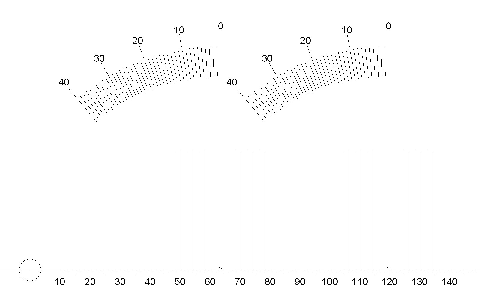
Protractor
This protractor is set for a playing radius of 58-146.3mm. As such it has zero points at radii of 63.6mm and 119.6mm. The files were created at 10 dots/mm for precise millimeter drawing and should print well. For now I recommend downloading the PDF version of the protractor as Adobe Acrobat is a universial program. On the downside the PDF version seems to suffer a little from much higher compression. The JPEG version may print best from within an appropriate graphics program.Notice: From Windows 7 the PDF file prints to correct dimensions from Adobe Acrobat. The JPEG version also prints correct from my graphics program but not from Window Preview. Linux will print the PDF version of the protractor with Adobe Acrobat 9.5.5. This version of the acrobat reader is no longer offered by Adobe but is still available on the internet. Since Mac OS X and Linux share much code, you might try Acrobat for Mac. I haven't yet. Outside of Adobe Acrobat you may have to experiment to get the correct results.
| Figure 7: Turntable Geometry protractor with Offset Angle Guides |
 |
Alternative PDF version
Use instructions
- Download file and print file.
- If using the JPEG file, right click on the file, select Save Image As, and choose a directory, and click save.
- If using the PDF version, simply click the link and follow the directions to save, or right click on the file, select Save As, and choose a directory, and click save.
- Print file with print options set to exact size rather than fit
or scale.
- Verify millimeter scale with ruler to ensure correct print
sizing. 1 inch = 25.4mm.
- Glue the printout to a record thickness cardboard substrate if desired.
- Cut the spindle hole.
- If only using paper, a hole punch punches a smaller hole than desired but you can still nibble the hole out to the correct size.
- If the protractor is mounted to a thicker substrate requiring
drilling, the official specification for spindle holes is 0.286
+0.001 –0.002 inches. Some have said that a 9/32" drill will
create the desired hole. Apparently they expect vibration to ream
a slightly larger than 9/32" hole.
- The cartridge is then aligned so that the stylus is perpendicular to the radius line from the spindle at the two zero points. Ordinarily this would be a trial and error process requiring adjustment of overhang values until the cartridge aligns at both points.
- However offset angle indicators are provided for each zero point. These would allow alignment with little trial and error if the line from the zero point to the tonearm pivot is made to pass the appropriate angle indicator at the correct offset angle calculated for the cartridge. It might be useful to draw lines on the protractor with a straightedge to help the angle alignment. If the alignment at one zero is done at the correct angle with respect to the pivot the other zero will be correct as well and need only be verified for accuracy.
- It is more important that the inner zero radius be aligned
correctly than the outer due to the increase in distortion as the
radius is shortened for any error angle.
Final remarks
Updates may be made later, such as the detailed calculations used in
the calculator and other things.|
|
Source 1 was for exact mathematics, except that I rederived the zero point calculations to determine full accuracy for constants specified only to four digits. Source 2 was used to verify the correct application of the mathematics.
1J. K. Stevenson, "Pickup Arm
Design," Wireless World, May
and June 1966.
2Noel Keywood, "Arm Geometry," updated
from Hi-Fi Answers, October 1979, Hi-Fi
World,
www.hi-fiworld.co.uk
Document History
October 26, 2015 Created.
October 26, 2015 Only PDF protractor prints correctly, and only
on Windows, troubleshooting.
October 29, 2015 Added explanation of overhang to the end of the
theory section.
November 14, 2015 Added |φerr/r| graph to calculator
to give feedback that calculations are correct.