 |
| Home │ Audio
Home Page |
Copyright © 2013 by Wayne Stegall
Created September 17, 2013. See Document History at end for
details.
Square Law
How the square-law
of field-effect devices arises from physics.
Introduction
I thought it important to know whether the square law transfer characteristic of FETs and vacuum tubes is arbitrary or concretely derived from some exact scientific principle. If it were arbitrary then different devices could vary in their adherence to the arbitrary model leading to unpredictable results. If based on a principle, more certain expectations could be held about their operation. At first thought, it seems possible that principle could be involved because the capacitor energy equation has a square-law characteristic as well.| (1) |
e = CV2 |
The Principle
Further inquiry has revealed the actual principle. That is that
the control mechanism does not depend on the control voltage
alone. Rather the voltages throughout the electric field all
contribute to the control mechanism in a distributed way. In the
case of a MOSFET the incremental contribution of voltages at each point
along the electric field to the total drain current could be
represented by the following equation.| (2) |
di dv |
= 2kn(v - VT) |
Then the entire current response could be found by integrating across the range of voltages distributed across the electric field.
| (3) |
ids = |
∫ | vgs VT |
2kn(v - VT) dv |
Now solve the integral
| (4) |
ids = |
 |
vgs VT |
kn(v - VT)2 |
| (5) |
ids = kn(vgs - VT)2 – kn(VT - VT)2 |
The result is the familiar square-law MOSFET equation.
| (6) |
ids = kn(vgs - VT)2 |
Abstractly, this result would have been anticipated without detailed math from recognizing that the integral of a simple linear relation is always a second order polynomial. Note also that the original thought that the controlling factor might be the energy in the gate or grid capacitor is a parallel coincidence. This is because the energy in a capacitor is calculated by similarly structured math.
The effect of a non-linear electric field
All this presumes that the electric field is linear with physical
distance (x), that is that v(x) = ax + b. If a device had a
non-linear field the calculations would be complicated by adding a
field voltage function v(x) = f(x) and the calculation would have to be
integrated with respect to x. The JFET creates such a
dilemma. Its gate diode capacitance is a function of voltage,
leading to a non-linear electric field. The capacitance of the
reversed biased p-n junction operates as if plate separation increased
with voltage so that the capacitance has an inverse square root
relationship to the control voltage something like:| (7) |
CPN
= |
|
After the transfer curve is computed from the non-linear electric field, the JFET has a 3/2 power law transfer characteristic in a form close to a square-law.1
| (8) |
ids = Ip0 |
 |
1 + |
3vgs
Vp0 |
+ 2 |
|
– | vgs
Vp0 |

|
3/2 |
|
This result is not so bad in comparison as shown below in figure 1; at least it is not exponential.
| Figure
1:
Comparative
plots of JFET and depletion MOSFET transfer curves |
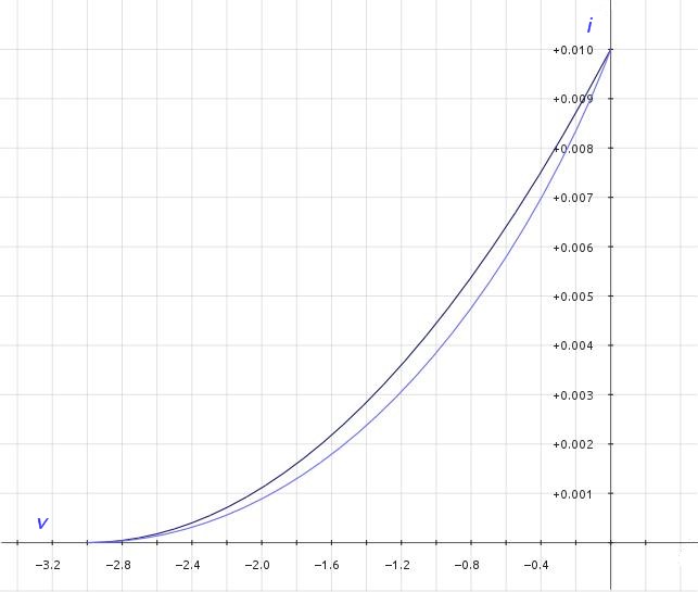 |
| Legend: ———— Depletion MOSFET transfer curve ———— JFET transfer curve |
Comparisons
Vacuum tubes derive their square-law transfer curve from the same field effect. Perhaps they could be regarded as Vacuum FETs for the sake of comparison. To some like me, this gives hope that MOSFETs can produce tube-like results without the extra design complexities of tubes: high voltages, heater circuits, and output transformers. However there is reason to believe tubes' square-law relationships are more pure. First the dielectric properties of a vacuum are considered perfect and that of the inert gases usually filling tubes them nearly so. The silicon dioxide or glass dielectric of the MOSFET is not as linear with a dissipation factor of 0.001,2 although a non-linearity so small could hardly be expected to produce a bad result. Also, the MOSFET tends to divide its gate capacitance – and therefore is electric field – between source and drain at the pinch off point in dynamic way as the the device operates. The vacuum tube does not seem to have any of these other possible field-distorting affects, its grid to cathode electric field unimpeded from pure operation.Finally
These distinctions only apply with certainty if the compared devices are not under feedback in any way. As soon as local feedback is applied, the resulting circuits – even the JFET ones – no longer have a square-law transfer curve although they still show square-law tendencies by showing dominance of the second harmonic in their distortion profiles.3|
|
1Donald L. Schilling and Charles Belove, Electronic Circuits:
Discrete and Integrated (New York, 1979), p. 138 equation 3.1-5.
2Arthur B. Williams and Fred J. Taylor, Electronic Design Handbook
(New York, 1981), p. 10-3
3See article Feedback Distortion Analysis.
Document History
September 17, 2013 Created.