 |
| Home │ Audio
Home Page |
Copyright © 2015, 2016 by Wayne Stegall
Updated May 3, 2016. See Document History at end for details.
Digital Phono Equalization
Introduction
Some may want to equalize their vinyl digitally for some reason. For one, some modern preamps are all digital, requiring digital equalization. Others, wanting to record their LPs to their computer, attribute some benefit to equalizing their collection without the sonic defects attributed to circuits with analog capacitors. I attempt here to address the latter interest mainly, although it has application to the former as well.Some concise theory
Most are accustomed to representations of filter function in Laplace
terms in the s-domain. However, digital filters are native to
another domain known as the z-domain. Fortunately, the two are
related and ideas in one can be translated to the other.In this case we expect RIAA equalization to be represented by
| (1) |
H(s) = |
(s – z1)
(s – p1)(s – p2) |
where z1 ,p1, and p2 represent turnover frequencies defined as
| (2) |
ω = 2πf0 |
To transform our equation to the z-domain required for digital analysis every element in H(s) is transformed by
| (3) |
z = esT, where T = | 1
fs |
the inverse of the sampling
frequency. |
In particular new poles and zeros are calculated
| (4) |
p(z) = ep(s)T, where p(s) is in natural frequency ω = 2πf0 |
In full the calculation is
| (5) |
p(z) = e |
2πf0
fs |
The transformed response equation has a similar appearance
| (6) |
H(z) = |
z
– z1
(z – p1)(z – p2) |
In order to obtain filter coefficients the separate pole and zero factors must be multiplied out to a full polynomial in the numerator and denominator.
| (7) |
H(z) = |
z
– z1
z2 + (– p1– p2)z + p1p2 |
Once normalized and adjusted for gain, the filter coefficients emerge.
| (8) |
H(z) = |
b0 + b1z-1 1 + a1z-1 + a2z-2 |
If it appears that I have careless in factoring multiplying or dividing out entire factors of z, z or z-1 alone as a factor only represents advance or delay of T length time periods respectively.
When the frequency and phase response are to be evaluated, Euler's law puts all frequencies on a unit circle where frequency is represented by the angle.
| (9) |
ejωT = cos(ωT) + sin(ωT)j |
For convenience frequencies are often made relative to the sampling frequency.
| (10) |
ωz = ωT = | ω
fs |
| (11) |
fz = fT = | f
fs |
Then the upper frequency limit of ½fs limits z-domain frequencies to the ranges –π < ω < π and -0.5 < f < 0.5.
IIR vs FIR
There are two major types of digital filters, FIR and IIR, that is
finite impulse response and infinite impulse response
respectively. Only the IIR filter is a direct equivalent to an
analog filter because only it has the poles that every analog filter
must possess. Equalization can be done with a FIR filter which
has all zeros. However, the FIR filter would have many zeros that
only imperfectly duplicated the poles. You can illustrate this by
doing long division on the IIR equation. The resulting infinite
zeros of the resulting FIR filter would then have to be truncated to
enable finite computations resulting in frequency ripple that the IIR
filter would not have. Be sure too the the FIR filter was not
linear phase or the equalization would not be phase correct.
Because of this the design that proceeds is an IIR design.Numerical calculations
The fact that sampling frequency enters calculation of poles and zeros
means that different filter coefficients have to be calculated for
every combination of sampling frequency and gain. Therefore a
computer program such as in figure 1
below is useful to calculate the desired filter. In Linux – and
maybe OS X as well – just paste the program in to a file named
riaaiir.c and execute the gcc compiler.- gcc riaaiir.c -lm -o riaaiir
- chmod +x riaaiir
- ./riaaiir
| Figure
1:
riaaiir.c
program
listing |
#include <stdio.h> #include <string.h> #include <math.h> typedef struct {int nn, nd; double n[3], d[3];} biquad; #define TP1 3180e-6 #define TP2 75e-6 #define TZ1 318e-6 #define TZ2 3.18e-6 #define PZ(T) exp(-1.0/(fs*(T))) biquad computeriaaiir(double fs, double dcgain, int extrazero) { static biquad bq; double p1, p2, z1, z2, gain; int i; p1 = PZ(TP1); p2 = PZ(TP2); z1 = PZ(TZ1); z2 = PZ(TZ2); bq.nd = 3; bq.d[0] = 1.0; bq.d[1] = -p1-p2; bq.d[2] = p1*p2; if(extrazero) { bq.nn = 3; bq.n[0] = 1.0; bq.n[1] = -z1-z2; bq.n[2] = z1*z2; } else { bq.nn = 2; bq.n[0] = 1.0; bq.n[1] = -z1; bq.n[2] = 0.0; } gain = (bq.n[0]+bq.n[1]+bq.n[2])/(1.0+bq.d[1]+bq.d[2]); for(i=0; i<3; i++) bq.n[i] *= (dcgain/gain); return bq; } void printbiquadcoeff(biquad bq) { int i; printf("Coefficients for H(z):\n\n"); printf("num"); for(i=0; i<bq.nn; i++) { printf("[%1d] = %e",i,bq.n[i]); if(i<bq.nn-1) printf(", "); } printf("\n--------------------------------"\ "--------------------------------\n"); printf("den"); for(i=0; i<bq.nd; i++) { printf("[%1d] = %e",i,bq.d[i]); if(i<bq.nd-1) printf(", "); } printf("\n\n"); printf("Audacity Nyquist biquad equations (LISP format)\n"); // a's are denominators printf("(biquad s b0 b1 b2 a0 a1 a2)\n"); printf("(biquad s"); for(i=0; i<3; i++) printf(" %e",bq.n[i]); printf(" 1.0"); for(i=1; i<3; i++) printf(" %e",-bq.d[i]); printf(")\n"); printf("(biquad-m s b0 b1 b2 a0 a1 a2)\n"); printf("(biquad-m s"); for(i=0; i<3; i++) printf(" %e",bq.n[i]); for(i=0; i<3; i++) printf(" %e",bq.d[i]); printf(")\n\n"); } int main() { biquad riaa; double fs, gain; int extrazero; do printf("\nEnter sampling frequency, dc gain, and 0/1 for extra zero: "); while(3 < scanf("%lf%lf%d",&fs,&gain,&extrazero)); printf("\n"); riaa = computeriaaiir(fs,gain,extrazero); printbiquadcoeff(riaa); printf("\n"); return 0; } |
Click here to download Windows version of the program.
Simulating the filter
After the calculated coefficients are applied to the equation for H(z),
that equation can be used to plot the expected frequency and phase
responses. Figure 2
below shows a plot of the RIAA filter calculated at the CD audio
sampling rate.| Figure
2:
Plot
of
H(z)
for
coefficients
calculated
for
44.1kHz. |
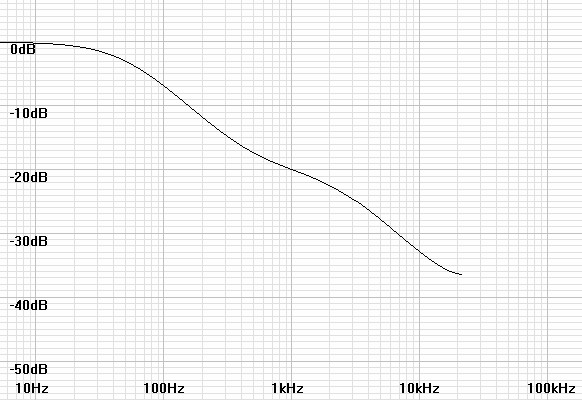 |
Notice in this plot that near the frequency limit at ½fs the response turns back up as if an extra zero near that frequency were applied. This is a recognized anomaly. I suspect that phase compression that locks all phases to 0º or 180º – whichever is nearer – forces an analog response approaching ½fs that is consistent with the compelled phase: thus the appearance of an added pole. The solution seems to be to raise fs until the anomaly does not affect the audio band. The following plots of filters calculated at higher sampling frequencies illustrate the latter conclusion.
| Figure 3: Plot of H(z) for coefficients calculated for 96kHz. |
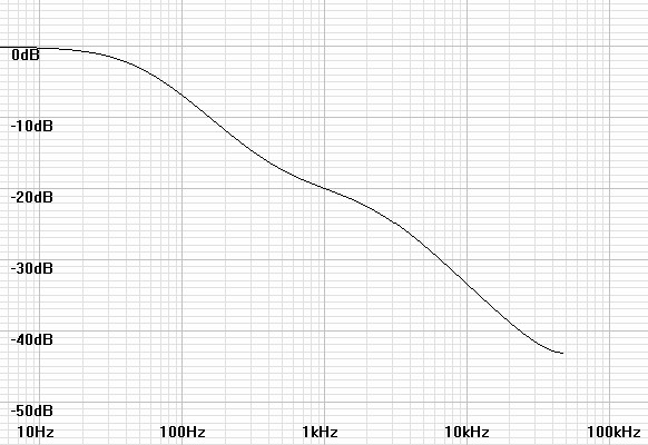 |
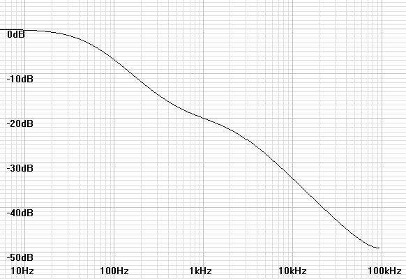
Figure 4: Plot of H(z) for coefficients calculated for 192kHz. |
 |
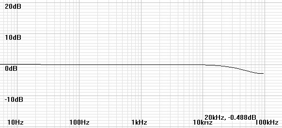
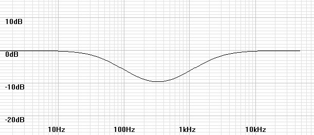
The filter plots alone do not show exactly how the frequency response is affected by the anomaly. Therefore the following plots add the filter response to that of an analog inverse RIAA filter to predict the actual final response.
| Figure
5:
Plot
of
H(z)
for
coefficients
calculated
for
44.1kHz
with
inverse
RIAA. |
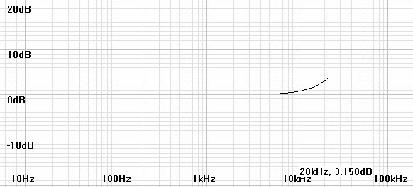 |
Figure 6: Plot of H(z) for coefficients calculated for 96kHz with inverse RIAA. |
 |
Figure 7: Plot of H(z) for coefficients calculated for 192kHz with inverse RIAA. |
 |
As a practical matter the RIAA specification creates an impossible inverse RIAA filter - one with more zeros than poles - which is unrealizable in a real analog filter. A realizable analog inverse RIAA filter would have to add an extra pole at some arbitrarily high frequency. Reliable sources say that the predominant extra pole was at 50kHz. Therefore it is reasonable to ask whether this pole would mitigate the rise in the response at the anomaly. The following plots investigate this possibility.
| Figure
8:
Plot
of
H(z)
for
coefficients
calculated
for
44.1kHz
with
practical
inverse
RIAA. |
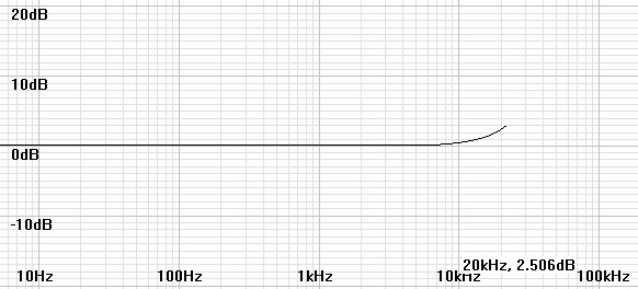 |
Figure 9: Plot of H(z) for coefficients calculated for 96kHz with practical inverse RIAA. |
 |
Figure 10: Plot of H(z) for coefficients calculated for 192kHz with practical inverse RIAA. |
 |
The extra pole seems to benefit the 44.1kHz filter little, to compensate the 96kHz filter nearly perfectly, and to roll off the 192kHz filter only slightly.
Applying the filter to an audio file
At this point you might expect a program to equalize your files.
However, I have found that a free audio editor - Audacity - has the
facility to apply the calculated filters. I presume the program
user-friendly to the degree that you can load your files and find your
way around. Once the file is loaded execute the following
procedure.- Connect turntable to an unequalized microphone input of a computer recording interface or stand-alone digital recorder.
- Record the LP with as much gain as will not clip the recorder. If insufficient maximum gain causes excessive noise, a separate low-noise amplifier may be interposed between the turntable and recorder.
- Open or import the recorded file into Audacity.
- Setup Audacity to show where clipping occurs. Then red
vertical lines will indicate clipping points.
Menu
→ View → Show Clipping
- Upsample the file if its sampling rate is less than
88.2kHz. It is thought better to upsample by some power of
2: 2x, 4x, etc.
Menu
→
Tracks → Resample
- Open the Nyquist prompt
Menu
→
Effects → Nyquist prompt...
- Enter the nyquist biquad equation that the program
generated. Note: If the
dialog contains a check box labeled "Use legacy (version 3) syntax,"
check it. My current software only gives equations in LISP format
not the newer SAL.
Example at 96kHz for a gain of one:
(biquad-m s 1.315951e-02 -1.273543e-02 0.000000e+00 1.000000e+00 -1.867054e+00 8.674785e-01)
(biquad-m s 1.315951e-02 -1.273543e-02 0.000000e+00 1.000000e+00 -1.867054e+00 8.674785e-01)
- If the gain changes to appear to clip, undo that step and find a way to proceed without clipping. At the actual filter step, recalculate the filter with an appropriate new gain and re-execute.
- Make other alterations as desired: click removal, warp or rumble filtering.
- Resample to original rate if desired.
- Save project or export file. Exports 16-bit audio by
default. Exporting 24 or 32 bit audio requires extra steps:
Menu →
File → Export Audio...
Save as type: Other uncompressed files.
Click Options... and select header and encoding appropriate for the desired 24 or 32 bit export.
Click Save.
Save as type: Other uncompressed files.
Click Options... and select header and encoding appropriate for the desired 24 or 32 bit export.
Click Save.
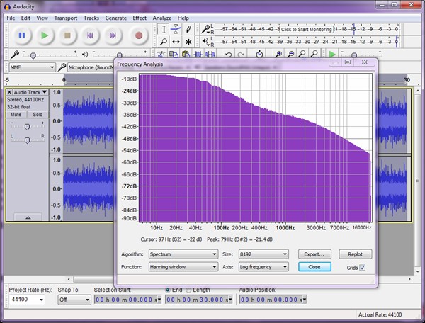
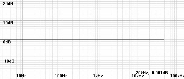
| Figure
11:
FFT
shows
that
upsampling
to
176.4kHz
before
equalization
to
return to 44.1kHz leaves no apparent anomaly. |
 |
Current Input Preamplifier Additions
It seems that the extra zero available to the digital biquad filter
could be used to implement equalization for a current-input
preamplifier instead of the 50kHz extra zero that seems not to be
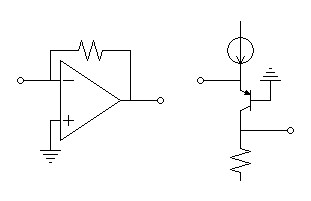
needed for the voltage-input preamplifier already calculated. Figure 12 shows both op-amp and
transistor current-input preamplifiers in the simplest form without
added detail. In such a configuration, the input loop between the
cartridge and preamplifier is a simple first-order lowpass filter
determined by the inductance and resistance of the cartridge in use.| (12) |
fLR
= |
R 2πL |
Caveat: Since figure 12 represents additional amplification, it might not be practical to drive a microphone preamplifier of already correct gain for a MM cartridge. Instead it could be used as a MC pre-preamp or drive a line-level ADC input instead.
| Figure
12:
Representative
linear
transimpedance
amplifiers
suitable
for
current
input
preamps. |
 |
The program has been altered so that entering an actual zero frequency instead of logical zero or one will calculate the biquad for the indicated current-input equalization. To begin you will have to obtain L and R values for your cartridge by measurement or documentation. These values can be obtained for some cartridges from the PhonoLCR program elsewhere on this site. Then calculate the LR frequency and enter it with the other parameters. The program will calculate a voltage-input equalization as before if logic zero or one values are entered for the zero.
| Figure 13: riaaiir.c program listing adding option of current input zero. |
| #include <stdio.h> #include <string.h> #include <math.h> typedef struct {int nn, nd; double n[3], d[3];} biquad; #define TP1 3180e-6 #define TP2 75e-6 #define TZ1 318e-6 #define TZ2 3.18e-6 #define PZ(T) exp(-1.0/(fs*(T))) biquad computeriaaiir(double fs, double dcgain, double extrazero) { static biquad bq; double p1, p2, z1, z2, gain; int i; p1 = PZ(TP1); p2 = PZ(TP2); z1 = PZ(TZ1); if(extrazero > 1.0) z2 = PZ(1.0/(2*acos(-1.0)*extrazero)); else z2 = PZ(TZ2); bq.nd = 3; bq.d[0] = 1.0; bq.d[1] = -p1-p2; bq.d[2] = p1*p2; if(extrazero) { bq.nn = 3; bq.n[0] = 1.0; bq.n[1] = -z1-z2; bq.n[2] = z1*z2; } else { bq.nn = 2; bq.n[0] = 1.0; bq.n[1] = -z1; bq.n[2] = 0.0; } gain = (bq.n[0]+bq.n[1]+bq.n[2])/(1.0+bq.d[1]+bq.d[2]); for(i=0; i<3; i++) bq.n[i] *= (dcgain/gain); return bq; } void printbiquadcoeff(biquad bq) { int i; for(i=0; i<bq.nn; i++) printf("\t%e",bq.n[i]); printf("\n------------------------------------------------\n"); for(i=0; i<bq.nd; i++) printf("\t%e",bq.d[i]); printf("\n"); printf("Audacity biquad equations\n"); // believe a's are denominators printf("(biquad s b0 b1 b2 a0 a1 a2)\n"); printf("(biquad s"); for(i=0; i<3; i++) printf(" %e",bq.n[i]); printf(" 1.0"); for(i=1; i<3; i++) printf(" %e",-bq.d[i]); printf(")\n"); printf("(biquad-m s b0 b1 b2 a0 a1 a2)\n"); printf("(biquad-m s"); for(i=0; i<3; i++) printf(" %e",bq.n[i]); for(i=0; i<3; i++) printf(" %e",bq.d[i]); printf(")\n\n"); } int main() { biquad riaa; double fs, gain; double extrazero; do { printf("\nExtra zero options:\n0: No extra zero\n1: Extra zero at 50kHz" \ "\n>1: Frequency of extra zero to compensate for lowpass rolloff of current input preamp"); printf("\n\nEnter sampling frequency, dc gain, and 0/1/f(current input LR freq) for extra zero: "); } while(3 < scanf("%lf%lf%lf",&fs,&gain,&extrazero)); printf("\n"); riaa = computeriaaiir(fs,gain,extrazero); printbiquadcoeff(riaa); printf("\n"); return 0; } |
Click here to download Windows version 1.1.0 of the program with option of current-input zero. This Windows version requires a check mark be placed for any extra zero, then if the zero frequency entry is blank the default is 50kHz, otherwise the input value is taken.
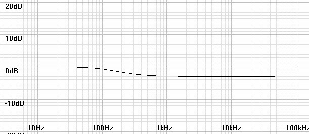
Figures 14 and 15 simulate the equalization and final responses of a typical current-input setup (perhaps some Pickering cartridges). Notice that the final response nearly has nearly no anomaly because the phase shift approaching ½fs is nearly zero.
| Figure 14: Plot of H(z) for coefficients calculated for fs = 96kHz and fLR = 212.2Hz. |
 |
| Figure 15: Plot of H(z) for coefficients calculated for fs = 96kHz and fLR = 212.2Hz with inverse RIAA. |
 |
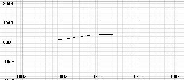
It may be that the L and R values used for your cartridge are inaccurate so that trial and error adjustments may be made to fLR. The mismatch between a pole and a zero in the equalization creates a shelf filter like a bass or treble control and likewise can be adjusted by a sharp ear as the following graphs indicate.
| Figure 16: Equalized with fLR = 212.2Hz but actually fLR = 150Hz. Adjust fLR down. |
 |
| Figure 17: Equalized with fLR = 212.2Hz but actually fLR = 300Hz. Adjust fLR up. |
 |
Result of an actual test recording
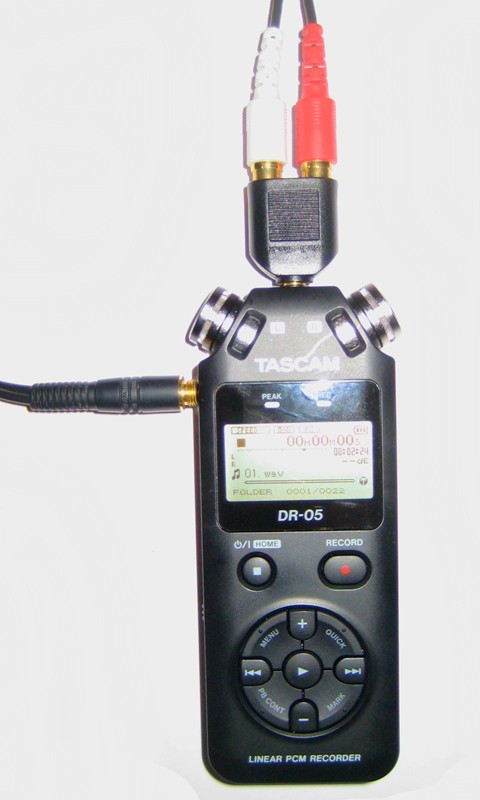
| Figure
18:
Tascam
DR-05
Digital
recorder
setup
to
record
directly
from
turntable. |
|
| The idea for this article was
actually based on recording directly to a high-resolution field
recorder that I already possessed: a Tascam DR-05 purchased from
Amazon.com for $89. Before recording, I calculated the frequency response in PhonoLCR using the recorder's specified 25kΩ input impedance without changing the estimated capacitance to get near Butterworth response in order to estimate what changes in sound I might expect from the different cartridge loading. I connected my turntable directly to the MIC/EXT IN input and recorded according to the recorder's instructions at 24bit/96kHz. The recording level set to a level somewhere in the middle of the range, suggesting a good fit to the output of the MM cartridge that I was using. Monitoring on the headphones, pops and crackles were very loud but I expected later equalization to greatly lower it. When finished, I equalized the recording in Audacity as I have detailed above. The first gain setting looked clipped so I recalculated the filter coefficients and tried again for correct results and returned the file to the recorder. I only intended to verify that the equalization sounded correct, which it did. The recorder's noise floor also seemed well below that of the album as well. Many years ago I had recorded the same album with a CD recorder. Those results, though they seemed accurate, seemed flat compared to listening to the vinyl while the recording proceeded. The vibrant colors of the vinyl seem muted somehow. In contrast, this high resolution recording has the vivid colors like the album, perhaps better because the treble sounded more neutral, something I attributed to cartridge loading. A test of current-input equalization await another time. |
 |
Inverse RIAA equalization additions
The new version of the program has added an inverse RIAA digital filter
function. It seemed an easy addition that may be useful to
someone. Perhaps it could create a test file to test the
equalization of a phono preamp or to create preequalized masters for
creating vinyl if record cutters allow any bypass of their inverse
equalization filters.Figure 19 below gives the listing of the expanded console program. All functionality is the same as before except for an additional variable entry to choose the inverse function. Then if the inverse function is chosen, the program swaps the numerator and denominator coefficients before they are adjusted for the specfied gain.
| Figure
19:
Version 1.2.0 riaaiir.c
program
listing
adds an inverse RIAA digital filter
function. |
| #include <stdio.h> #include <string.h> #include <math.h> typedef struct {int nn, nd; double n[3], d[3];} biquad; #define TP1 3180e-6 #define TP2 75e-6 #define TZ1 318e-6 #define TZ2 3.18e-6 #define PZ(T) exp(-1.0/(fs*(T))) biquad computeriaaiir(double fs, double dcgain, double extrazero, int inverse) { static biquad bq; double p1, p2, z1, z2, gain, tmp; int i, itmp; p1 = PZ(TP1); p2 = PZ(TP2); z1 = PZ(TZ1); if(extrazero > 1.0) z2 = PZ(1.0/(2*acos(-1.0)*extrazero)); else z2 = PZ(TZ2); bq.nd = 3; bq.d[0] = 1.0; bq.d[1] = -p1-p2; bq.d[2] = p1*p2; if((int)extrazero) { bq.nn = 3; bq.n[0] = 1.0; bq.n[1] = -z1-z2; bq.n[2] = z1*z2; } else { bq.nn = 2; bq.n[0] = 1.0; bq.n[1] = -z1; bq.n[2] = 0.0; } if(inverse) { /* swap numerator and denominator */ for(i=0; i<3; i++) { tmp = bq.d[i]; bq.d[i] = bq.n[i]; bq.n[i] = tmp; } itmp = bq.nd; bq.nd = bq.nn; bq.nn = itmp; } gain = (bq.n[0]+bq.n[1]+bq.n[2])/(1.0+bq.d[1]+bq.d[2]); for(i=0; i<3; i++) bq.n[i] *= (dcgain/gain); return bq; } void printbiquadcoeff(biquad bq) { int i; for(i=0; i<bq.nn; i++) printf("\t%e",bq.n[i]); printf("\n------------------------------------------------\n"); for(i=0; i<bq.nd; i++) printf("\t%e",bq.d[i]); printf("\n"); printf("Audacity biquad equations\n"); // believe a's are denominators printf("(biquad s b0 b1 b2 a0 a1 a2)\n"); printf("(biquad s"); for(i=0; i<3; i++) printf(" %e",bq.n[i]); printf(" 1.0"); for(i=1; i<3; i++) printf(" %e",-bq.d[i]); printf(")\n"); printf("(biquad-m s b0 b1 b2 a0 a1 a2)\n"); printf("(biquad-m s"); for(i=0; i<3; i++) printf(" %e",bq.n[i]); for(i=0; i<3; i++) printf(" %e",bq.d[i]); printf(")\n\n"); } int main() { biquad riaa; double fs, gain; double extrazero; int inverse; do { printf("\nExtra zero options:\n0: No extra zero\n1: Extra zero at 50kHz" \ "\n>1: Frequency of extra zero to compensate for lowpass rolloff of current input preamp" \ "\nInverse options: (0) RIAA eq, (1) Inverse RIAA eq"); printf("\n\nEnter sampling frequency,\ndc gain,\n(0/1/f(current input LR freq)) for extra zero" \ "\n(0/1) to select inverse:\n\n: "); } while(4 < scanf("%lf%lf%lf%d",&fs,&gain,&extrazero,&inverse)); printf("\n"); riaa = computeriaaiir(fs,gain,extrazero,inverse); printbiquadcoeff(riaa); printf("\n"); return 0; } |
Click here to download Windows version 1.2.0 of the program with inverse RIAA option. This Windows version requires a check mark be placed to invoke the inverse function. As before, it also requires check mark be placed for any extra zero, then if the zero frequency entry is blank the default is 50kHz, otherwise the input value is taken. Also note that any extra zero specified becomes a pole in the inverse filter.
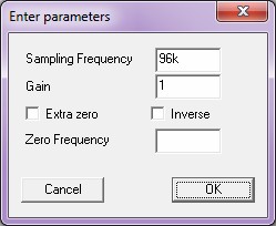
| Figure
20:
Entry
dialog
for version 1.2.0 of the Windows program |
 |
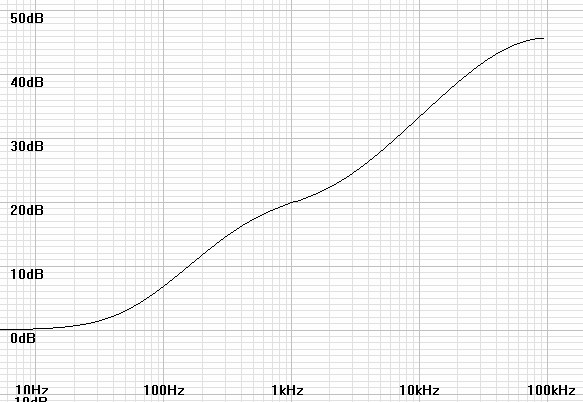
I verified the results by plotting frequency response for many combinations of combined RIAA and like specified inverse RIAA filters to get perfectly flat responses in all cases. Having proven that the inverse filters are exact inverses their response can be inferred by examining the responses of the corresponding non-inverted plots above.. Figure 21 below shows a representative inverse RIAA response.
Figure 21: Plot of H(z) for coefficients calculated for 192kHz inverse filter with extra pole. |
 |
Final remarks
You might argue that Audacity has a FIR RIAA filter built in, however
blogs inquiring whether they had correct or linear phase resulted in
someone saying that phase correction did not matter. This
uncertainty leaves me another reason to stay with an IIR design.This is a large topic. Therefore there may be later additions.
|
|
Document History
June 6, 2015 Created.
June 11. 2015 Corrected a misspelling and added an extra step to
each of the compilation of riaaiir and the Audacity filtering process.
September 1, 2015 Added capability to digitally equalize a
current-input preamplifier.
September 7, 2015 Added Results of an actual test recording.
May 3, 2016 Added inverse RIAA functionality to software.