 |
| Home │ Audio
Home Page |
Copyright © 2011 by Wayne Stegall
Updated November 4, 2011. See Document History at end for
details.
Phono Preamp Input Protection
Dilemma
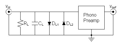
On first impulse it seems advisable to protect the front end of a phono preamp with a circuit such as in figure 1. The clamping diodes are able to protect from the real possibility that a line output could be connected to a phono input. However, reservations about the distortion produced by the diodes may deter their actual use. I expect you too have similar concerns. In view of their usefulness however, it would be better to analyze the circuit before making a hasty decision.| Figure
1:
Diodes
protecting
phono
preamp
input
|
 |
A Typical Example
A typical illustration of the need of input protection for a phono
preamp is illustrated in figure 2.
Here
a
typical
low-noise
bipolar
operational
amplifier
has
internal
protection
diodes
limited
to
10mA
to
protect. Without protection,
ZG may allow excessive current to flow through internal
diodes damaging an expensive operational amplifier. Discrete
circuits could present similar difficulties, i.e. an overloaded JFET
could see reverse gate current exceeding specifications in spite of
some
protection by a source resistor.| Figure
2:
Example
of
diodes
protecting
bipolar
operational
amplifier
|
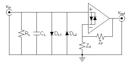 |
| ZF and ZG
here simplify a more complicated RIAA equalization circuit. Internal protection diodes are taken out of the signal path by the feedback loop in normal operation. |
Here the voltage across ZG causes the external diodes to shunt the majority of current that would pass through the internal diodes if the input is overloaded. Because diodes have an exponential transconductance characteristic, addition of voltages multiplies currents and subtraction of voltage divides currents by commonly known exponential and logarithmic relations.
| Exponential Axioms |
|
Corresponding Logarithmic Axioms |
||||||||||||||||||||
|
|


Where Ve is the limiting voltage across the external diodes, Vi that across the internal ones, and Vzg that across ZG, the following voltage subtraction creates a related current bypass ratio:
| (5) |
Vi = Ve - Vzg |
Solve for the current bypass ratio presuming external protection diodes have the same saturation current IO as the internal ones:
| (6) |
Iext
Iint |
= |
IO(e40×Ve -
1)
IO(e40×Vi - 1) |
= | e40×Ve - 1
e40×Vi - 1 |
Under the overload conditions of interest, e40×V >> 1, therefore:
| (7) |
Iext
Iint |
= |
e40×Ve
e40×Vi |
= | e40×(Ve-Vi) |
= |
e40×Vzg |
In the limiting condition where a ZG of 10Ω passes 10mA and drops 100mV:
| (8) |
Iext
Iint |
= |
e40×(100mV) | = | e4 |
= |
54.5982 |
This means the external protection diodes will bypass 545.982mA before the op-amp input diodes exceed their specifications, conditions easily met by reasonable overload conditions. This is well below the current output limit of most operational amplifiers and the output of circuits with limiting resistors as well. Only the improbable connection of speaker leads to the protected input could damage the operational amplifier. The sacrifice and replacement of a 1N914 or a 1N4148 small signal diode is well worth protecting more expensive circuitry, although a medium diode like a 1N4004 might absorb all current from any line output without destruction.
More Exact Calculations
My presumption in the above calculations that the saturation currents are equal served the purpose of demonstration, because I knew it to be a worst case example. Actual saturation current, however, is roughly proportional to the size and current capacity of the diode. I expected the operational amplifiers input protection diodes to be smaller than any external ones used for protection and to result in a greater current bypass ratio.If the presumption of equal IO were not met equation 7 would have been:
| (9) |
Iext
Iint |
= |
IO-ext
IO-int |
× e40×Vzg |
Consider some actual saturation currents:
| Diode |
|
IO |
|
|
|
|
| AD797 input protection |
1.0fA |
|
| 1N914 |
64.7335pA |
|
| 1N4001 |
31.9824nA |
Still in the limiting condition where a ZG of 10Ω passes 10mA and drops 100mV,
now an AD797 protected by 1N914's gives:
| (10) |
Iext
Iint |
= |
64.7335pA
1.0fA |
× e40×(100mV) | = | 64.7335k × e4 |
= |
3.53433M(A/A) |
and an AD797 protected by 1N4001's gives:
| (11) |
Iext
Iint |
= |
31.9824nA
1.0fA |
× e40×(100mV) | = | 31.9824M × e4 |
= |
1.74618G(A/A) |
Either of these real results leave the operational amplifer to bear negligible overload current.
SPICE Analysis
The following is the distortion analysis of a typical MM phono input
loop.| Figure 2: SPICE schematic. |
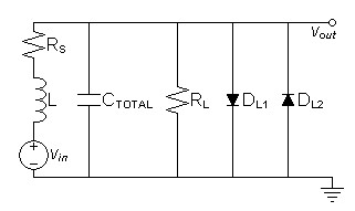 |
SPICE model
Fourier analysis of vout for vin of 5mVRMS protected by 1N914s:
No. Harmonics: 16, THD: 6.20501e-06 %, Gridsize: 200, Interpolation Degree: 1
| Harmonic | Frequency | Magnitude | |
Norm.Mag | |
Percent | |
Decibels |
|
|
|
|
|
|
|
|||
| 1 | 1000 | 0.00696354 | 1 | 100 | 0 | |||
| 3 | 3000 | 3.5818e-10 | 5.14364e-08 | 5.14364e-06 | -145.775 | |||
| 5 | 5000 | 6.19818e-11 | 8.9009e-09 | 8.9009e-07 | -161.011 | |||
| 7 | 7000 | 7.47346e-11 | 1.07323e-08 | 1.07323e-06 | -159.386 | |||
| 9 | 9000 | 8.88345e-11 | 1.27571e-08 | 1.27571e-06 | -157.885 | |||
| 11 | 11000 | 1.03415e-10 | 1.48509e-08 | 1.48509e-06 | -156.565 | |||
| 13 | 13000 | 1.17256e-10 | 1.68386e-08 | 1.68386e-06 | -155.474 | |||
| 15 | 15000 | 1.29017e-10 | 1.85275e-08 | 1.85275e-06 | -154.644 |
Distortion here is vanishingly low!
I initially preferred the use of small signal diodes to medium ones because I expected the distortion to increase with the saturation current. So here I add a distortion analysis with a medium diode as well.
Fourier analysis of vout for vin of 5mVRMS protected by 1N4001s:
No. Harmonics: 16, THD: 0.000811766 %, Gridsize: 200, Interpolation Degree: 1
| Harmonic | Frequency | Magnitude | |
Norm.Mag | |
Percent | |
Decibels |
|
|
|
|
|
|
|
|||
| 1 | 1000 | 0.00696751 | 1 | 100 | 0 | |||
| 3 | 3000 | 5.65599e-08 | 8.11766e-06 | 0.000811766 | -101.811 | |||
| 5 | 5000 | 2.24354e-11 | 3.22001e-09 | 3.22001e-07 | -169.843 | |||
| 7 | 7000 | 1.34994e-14 | 1.93748e-12 | 1.93748e-10 | -234.255 | |||
| 9 | 9000 | 2.00863e-14 | 2.88285e-12 | 2.88285e-10 | -230.804 | |||
| 11 | 11000 | 4.37608e-14 | 6.2807e-12 | 6.2807e-10 | -224.040 | |||
| 13 | 13000 | 4.30256e-14 | 6.17517e-12 | 6.17517e-10 | -224.187 | |||
| 15 | 15000 | 1.82514e-14 | 2.6195e-12 | 2.6195e-10 | -231.636 |
The third harmonic here has increased as expected until it is low but no longer vanishing. It is odd that the remaining harmonics have decreased.
Last Word
Because diode distortion is presumed more objectionable than that of FETs and tubes, It is still a subjective matter whether an input protector's distortion is acceptable in your circuit.|
|
Document History
November 3, 2011 Created.
November 3, 2011 Made improvements. Added much new
material. Updated SPICE results based on better diode models.
November 4, 2011 Corrected some grammar.