Copyright © 2010
Created September 29, 2010. See Document History at end for
details.
A
Linear Logarithmic Volume Control
Introduction
Human
hearing
spans
a
volume
range
of
about
a
million
to
one.
In
order
to
hear
the
range
from
the
quietest
whisper
to the
loudest gun shot, sounds are scaled so that differences in volume are
heard in ratios rather than linearly. Every 2 to 1 difference in
sound
level registers about the same change regardless of absolute
level.
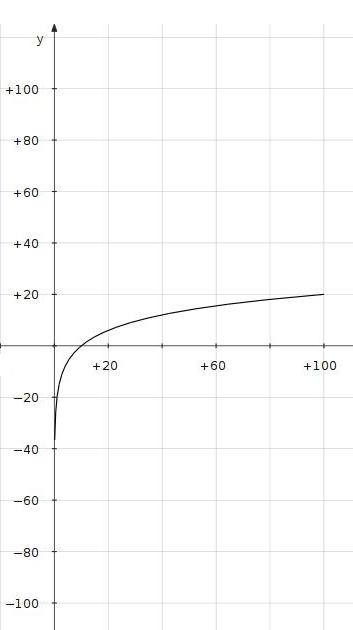
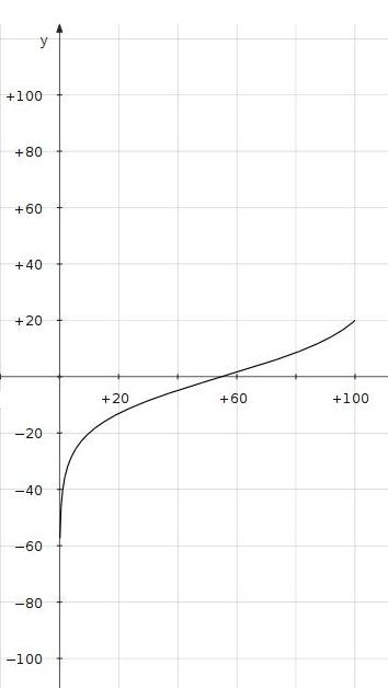
Thus it is said that our hearing scale is logarithmic. A
linear adjustment used
alone would only allow about 20dB of useful adjustment in its through
most of its range, the rest of the lower level crowded at the bottom of
the adjustment as shown in figure 1. For this
reason
audio volume controls are created with an uneven resistance pattern
meant to match logarithmic hearing as much as possible. This
graded resistance taper however would be expected to compare
unfavorably with a linear potentiometer with its even distribution of
resistance due to the difficulty and imprecision of modulation a
precisely changing resistance pattern. If somehow a circuit could
create a logarithmic gain change with a linear potentiometer, greater
volume accuracy and tracking between channels could be expected.
Now to present one circuit concept that accomplishes just this.
|
Figure 1: Logarithmic Plot of a
Linear
Control (x-axis is
%adjustment; y-axis is dB gain)
|
|
|
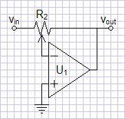
An Illustrative Circuit
| Figure 2: Control Circuit 1 |
|
A circuit putting
the resistance
of one end of the potentiometer in the numerator and the other in the
denominator of the gain equation would seemingly expand the range of
logarithmic gain change considerably. The circuit of figure 2 does just that. The
gain equation relative to control adjustment is:
AV
=
|
-
|
R2a
R2b
|
=
|
x
R2-x
|
|
where x
represents control adjustment from 0 - R2 on feedback side of the
wiper.
|
In normalized form the equation becomes:
AV =
|
-
|
x
1-x
|
|
where x
represents control adjustment from 0 - 1 on feedback side of the wiper.
|
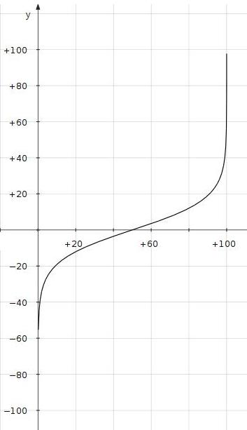
The plot of figure 3 to the
right shows a logarithmic range of approximately 40dB. At the
extremes of adjustment the gain goes to the extremes of zero and
infinity (In reality, limited to the open loop gain of the operational
amplifier.). A perfect logarithmic adjustment would never go to
zero gain (-infinity dB). As a result even a log-taper
potentiometer has a limited logarithmic range to allow the bottom
adjustment to drop to zero. This circuit is best to illustrate
the concept but is unfeasable due to possibility of infinite gain.
|
|
|
| Figure 3: Logarithmic Plot of
Control Circuit 1 (x-axis is %adjustment; y-axis is
dB gain) |
|
|
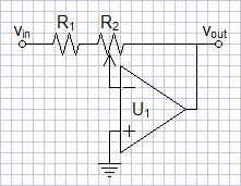
A More Practical Circuit
Figure 4: Control Circuit 2
|
|
The circuit of figure 2 above would be
improved by preventing infinite gain. The circuit of figure 4 adds a fixed resistor R1
before the potentiometer to this end. This resistor also prevents
the possiblity of the zero input impedance that would result at the
high extreme of adjustment. The plot of figure 5 now shows the
gain limited at the upper end of the logarithmic range. The
maximum
gain will be:
|
|
| Figure 5: Logarithmic Plot of
Control Circuit 2 (x-axis is %adjustment; y-axis is
dB gain) |
|
|
Spice Simulation
I generally expect simple op-amp circuits to function correctly as
their feedback circuits dictate. In spite of believing that an
op-amp stable for a gain of one in a non-inverting configuration could
operate down to a gain of zero in the inverting configuration, I needed
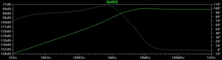
to verify my assumption. Modeling an LT1007 op-amp on LTSpice IV,
I could take the gain down almost to zero with no problems. At
zero gain a harmless anomaly cropped up:
Figure
6:
Zero
Gain
AC
SPICE
Analysis
|
|
Basically, this is a rise in the ultrasonic frequency response from
zero that
raises the 20kHz response to -133dB. I expect this is a voltage
divider effect between R1+R2 and a complex op-amp output
impedance. This is because output impedance of the op-amp will
rise above the dominant pole in a way consistent with these
results. Although this is of no real consequence, you can
eliminate
it by adding a small resistance into the feedback loop between v
out
and R
2.
Adding
a
value
of
10Ω
to
values
of
R
1=1.1kΩ and R
2=10kΩ
resulted in a fix with a limitation that gain could only be turned down
to
-60dB.
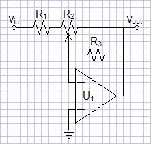
Final Circuit Correcting a Potential Operational Error
Figure
7:
Control
Circuit
3
|
|
|
A concern that might not be as
obvious has to be addressed. It is possible that the
potentiometer wiper could lose contact momentarily. This could be
a undetectably brief open during normal operation or worse if the
control becomes scratchy with age. In this event, the gain could
spike to the open loop gain of the operational amplifier, perhaps
damaging subsequent components. The insertion of an extra
parallel feedback resistor R3 of high value, as shown in the
circuit of figure 7, would
eliminate this concern. Now an open wiper will result in a
non-inverting buffer amplifying only ground and producing a safe
dropout of gain rather than a spike. A necessary
condition that R3 be much greater than R2 will
leave the gain approximately the same as before:
Values chosen for low noise and a maximum gain of nine might be
R1=1.1kΩ
R2=10kΩ
R3=1MΩ
Do not forget the varying input impedance. This circuit will have
to be preceded by a buffer, even if only a source follower.
|
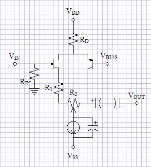
Discrete Difficulties
Figure
8:
Control
Circuit
4
|
|
|
This
concept
is
simply
implemented
with
operational
amplifiers.
The
circuits
required
for
discrete,
non-feedback
amplifiers
might
be
more
complicated than
the single-ended purist would like. However, I submit the circuit
of figure 8 as only a
suggestion for a possible topology.
The folded cascode bends the signal path so that R2 can be
in both the numerator and denominator of the gain equation. The
parallel capacitor turns the current source into a automatically-biased
voltage. R1 and R2 will adjust the voltage
gain as do the above circuits. The primary fault of the
circuit is that the voltage bias at the wiper of R2 changes
with the volume setting, creating a automatic bias readjustment
everytime the
volume is changed. Perhaps it is better to use op-amps regardless.
|
Document History
September 29, 2010 Created
