 |
| Home │ Audio
Home Page |
Copyright
©
2009
by
Wayne
Stegall
Updated December 1, 2015. See Document History at end for
details.
| g"> |
Linear Phase Sinc Compensation Filter
For Zero-Oversampling DACs
Introduction
This article pertains to the following graph of the frequency response of CD DAC output without oversampling:
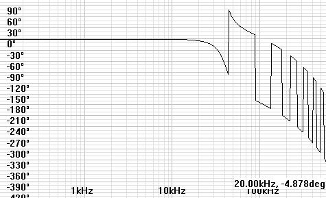
| Figure 1: Zero oversampling CD DAC response |
|
|
| Legend: Black: signal frequencies < 22.05kHz Blue: image frequencies > 22.05kHz |
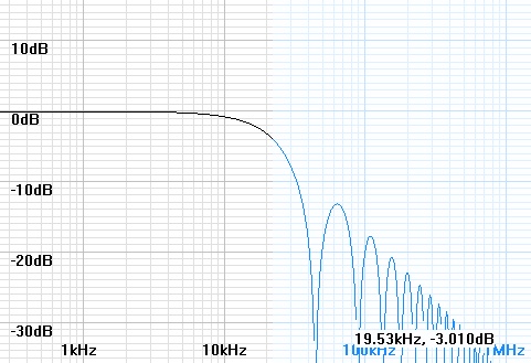
As you can see the frequency response is down 3dB
at 19.53kHz.
The envelope (an imaginary line drawn through the peaks) of the
stopband is
that of a first order lowpass filter with a break frequency of 14.037Hz
(=
44.1kHz / pi). There is no phase shift in the passband, but the
phase
alternates at each notch in the stopband. This response, called a
sinc
response, is the consequence of the output holding each digital sample
through
the entire sampling period. That the response falls off in the
region of
unwanted digital images supports the use of zero oversampling DACs
without filtering.
Although this response is very good in itself, someone might want to
extend it
flat to 20kHz or even 22kHz.
Solutions
1.
Because
the original response is very close to a second order Bessel
response
in the transition band, a first solution would be to reverse engineer a
fourth
order filter from the equivalent second order Bessel stage,
and
use the
added stage as the compensating filter. The resulting filter
specifies as a
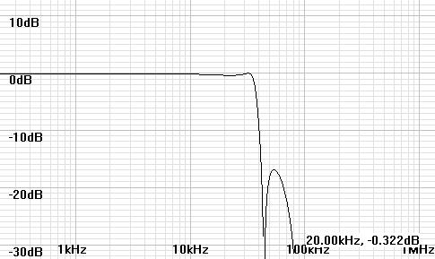
0.0127dB ripple Chebychev with a cutoff frequency of 32.41kHz.
Because the CD sinc
response sags in the transition band just a little more than the
equivalent second
order Bessel response used as a model, the final corrected response
only has
only one ripple peak of 0.043dB before falling to -0.001dB at
20kHz. This
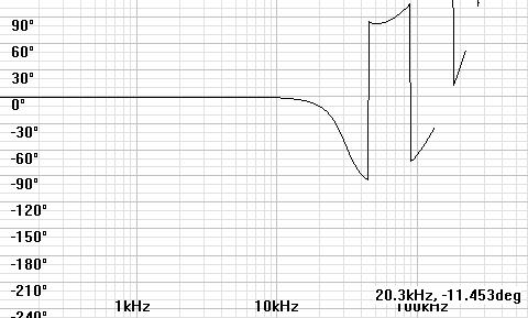
solution is less than ideal because of the ripple and the phase shift
of 11deg
at 20kHz.
| Figure 2: Solution 1 frequency response |
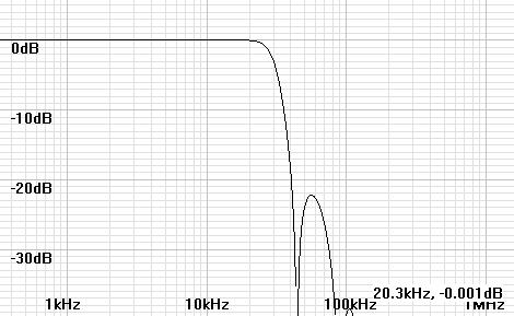 |
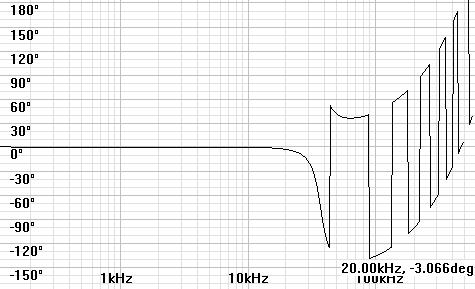
Figure 3: Solution 1 compensated phase response |
 |
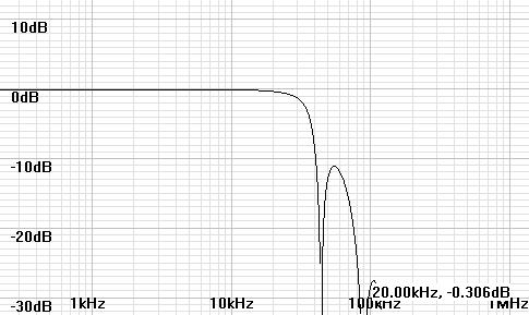
2. My original idea was that a first order zero and a second order pole could contribute to frequency compensation while canceling each’s phase contribution. This required more of a tinkering process than the other. More adjustment might approach closer to zero phase shift, however this is one of the better responses I have found. The frequency response rolls off without ripple and the phase at 20kHz is respectable. The first order pole at 100kHz is required to implement the zero because real systems must have as many or more poles than zeros. The combination is a shelf response like a treble boost that begins at the zero and ends at the pole.
| Solution 2: Filter Specifications: |
|
first order lowpass zero, f0=41kHz first order lowpass pole, f0=100kHz |
Figure 4: Solution 2 frequency response |
|
|
|
|
|
|
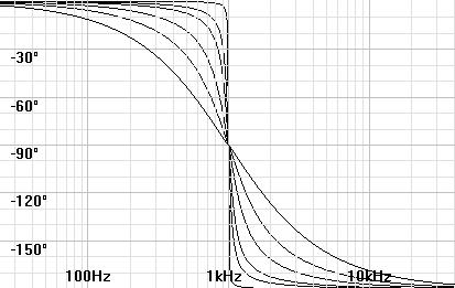
3. The pole-zero solution of solution 2 above was derailed in my mind when I realized that lowpass phase shift needed to be compensated for group delay in order to make realistic comparison of any competing solutions. (See article When is Phase Shift not Phase Shift?) After I provided myself means to make a compensated phase plot, I found a simpler solution. Figure 6 shows the basis for the solution. As Q goes up, phase shift becomes more localized around the resonant frequency while reducing passband phase shift. Compared to solution 1 above, the resonant frequency is pushed further into the first notch while the Q is increased. The result is the best solution of the three. The apparent ripple is in the first image beyond 22.05kHz. Up to that point the frequency response rolls off smoothly without ripple. Lowering the Q to 3 to eliminate the ripple in the first image will change the response at 20kHz to -0.439dB and phase shift to -3.958deg.
| Figure 6: Phase shift as Q goes from 0.5 to 100 |
|
|
Solution 3: Filter Specifications |
second order lowpass stage: f0=37kHz, Q=4 |
|
|
|
|
Figure 8: Solution 3 Compensated Phase Plot |
|
|
Application
The circuits for the second order lowpass
stages can
be designed with free software from:
www.ti.com –
FilterPro
active filter design software from Texas Instruments.
www.linear.com
- FilterCAD
active filter design software from Linear Technology.
A single-ended class A sallen and key filter
however might
require original design calculations because of the non-zero output
impedance
driving the positive feedback circuit.
The pole-zero circuit should come easy to those
familiar
with electronics.
|
|
Document History
January 26, 2009 Created.
January 26, 2009 Revised.
April 19, 2012 Made some style improvements, replaced image of
figure 1 with a more informative one, and replaced references to fc
with f0.
December 1, 2015 Improved formatting.