Copyright © 2018 by Wayne Stegall
Created February 6, 2018. See
Document History at end for
details.
Input/Output Bypass Board
Introduction
It is perhaps common that some optional components may be desired to
switch in and out of an audio system. Because of this some such
components have a bypass switch in addition to the power switch.
This works well, but it is possible to switch in the component with the
power off. Instead a relay board at the the input/output
terminals could bypass the component by default and only switch it in
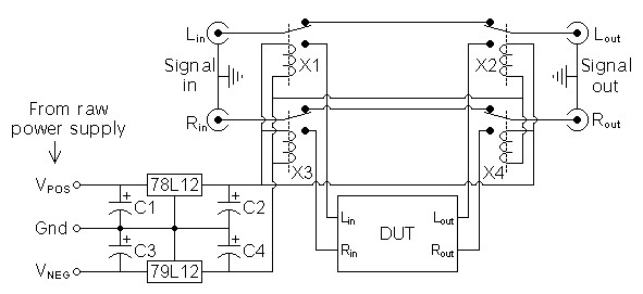
if the power is on. The circuit of
figure 1 below will accomplish this
task.
Circuit
Figure
1:
Schematic
of
I/O
relay
board.
|
|
Operation
In the given circuit DUT represents the audio component which is
switched in by relays X1-X4 which can be 4 SPDT or 2 DPDT relays.
The relays normally connect to bypass the component when not powered up
and switch to the opposite contact to connect the component with power
is applied. Because the same raw power supply with power the
component and relay board, the power switch with activate both
component power and connection.
Design Choices
When I examined possible relays, coil current seemed inversely
proportional to coil voltage. Therefore the largest coil voltage
that would work with the raw power supply would draw the least amount
of power. This choice I made to be 24V. Drive to the coils
would then be supplied by voltage regulators to prevent the nearness of
the coils to the signal from injecting hum. The TO92 regulators
suggested should be replaced with those in the usual TO220 package if
the relay coils require. A LM317 datasheet
suggested tantalum capacitors before regulators if they were at a
distance from the raw power supply, thus giving rise to choices for C
1
and C
3. C
2 and C
4.are not
required, you may omit them or choose any value you like. The
circuit board is constructed with jacks on one side and electronic
components on the other. If you like, reverse biased diodes of
the 1N4001 type could be paralled with C
2 and C
4
to protect the regulators.
Possible parts list.
| Lin, Rin, Lout,
Rout |
|
4
|
|
audio jacks
|
| X1 – X4 |
|
4
|
|
24V SPDT reed relay
|
(or)
|
|
2
|
|
24V DPDT reed relay (in X1/X2
and X3/X4 pairs)
|
|
|
1
|
|
78L12 12V voltage regulator
(TO92 package)
|
|
|
1
|
|
79L12 –12V voltage regulator
(TO92 package) |
| C1, C3 |
|
2
|
|
2.2µF tantalum capacitor
|
| C2, C4 |
|
2
|
|
100µF electrolytic capacitor
|
Final thoughts
I built and tested a similar circuit long ago.
Document History
February 6, 2018 Created.
