 |
| Home │ Audio
Home Page |
Copyright © 2013 by Wayne Stegall
Updated April 27, 2013. See Document History at end for
details.
Electrical-Mechanical Equivalence
Introduction
Electronics professionals and hobbyists sometimes want to analyze mechanical systems but are somewhat stuck in an electronics frame of mind. However passive mechanical systems function according to the same principles and mathematics as passive electronics.Mechanical "Circuits"
It seems reasonable to relate velocity to current since both relate to
movement and force to voltage because both act to cause movement.
It is fortunate that classical physics defines mechanical impedance in
just those terms. Therefore the various components of mechanical
impedance can be related to a functionally equivalent electronic
component. The following table clarifies these relationships.Figure 1: Electrical-Mechanical Equivalence Table
| Electronic Parameters |
|
Mechanical Equivalents |
||||||||||||
| Component |
Symbol |
Laplace Representation |
Defining Equation |
|
Component |
Symbol | Laplace Representation |
Defining Equation |
||||||
|
|
|
|
||||||||||||
| Voltage |
v |
⇔ | Force |
f | ||||||||||
| Current |
i |
⇔ | Velocity |
u | ||||||||||
| Resistance |
R |
R |
|
⇔ | Damping |
D | D |
|
||||||
| Inductance |
L |
sL |
|
⇔ | Mass |
M | sM |
|
||||||
| Capacitance |
C |
|
|
⇔ | Compliance |
K |
|
|
||||||
As a result, a mechanical system can be represented as a circuit, electronic in form but mechanically accurate in function. Creating a circuit however may at first be somewhat difficult because mechanical systems do not have or require a return path for velocity as electrical circuits do for current. However mechanical nodes that move locked together represent serial branches and those that allow independent movement under the same force suggest a parallel structure. After a circuit is constructed (or before if you have a mechanical mind) Laplace equations can be written and analysis undertaken by the usual electronics math.
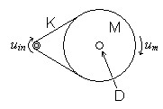
Example: Belt drive mechanism
Figure 2 below is a mechanical
system that those interested in turntables may want to analyze.
The mass (M) used would not be the total mass of the second pulley or
platter but the inertial mass along the edge where the belt runs, a
figure somewhat smaller. Likewise the damping (D) is that which
is seen
along the edge as well, having been reduced by mechanical leverage from
the higher value actually seen at the bearing.| Figure
2: Belt drive mechanism |
|
Figure
3: Belt drive schematic |
 |
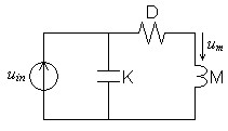 |
Figure 3 above shows the mechanical circuit representing this mechanical system. Note that D and M are connected in series because they move exactly together. K is seen in parallel with the others because it allows independent although related motion at each end.
Set up and reduce the Laplace equations for the transfer function of this mechanical circuit.
| (1) |
H(s) = |
um
uin |
= |
|
| (2) |
H(s) = |
1*
s2MK + sDK + 1 |
Take equation 2 in the standard second-order lowpass form of equation 3.
| (3) | 1 |
|||||
| H(s) = |
|
|||||
|
| (4) | 1 |
1 |
|||||
| ω = |
|
, therefore f = |
|
||||
|
|
| (5) |
Qω = |
1*
DK |
| (6) | Q = | 1
DKω |
= |
|
= |
1
D |
|
Transducers
Electromagnetic transducers complicate this understanding of equivalence. Functionally they are like transformers with an electrical circuit and its primary or secondary on one side. The functionality of a second winding is served by mechanical movement. Mechanical motion of the magnetic system replaces electron movement to satisfy the impetus on the other side of the interface. As compared to a transformer, turns ratio is replaced by force factor α, a defining characteristic of the transducer's magnetic system.| (7) | α = Bl |
Because the m is usually in the form of a cylindrical coil of wire, it is usually calculated from the number of turns of wire (N) and diameter (d) or radius (r).
| (8) | l = πNd |
| (9) | l = 2πNr |
The equations defining the transform at the transducer junction define an impedance inversion.
| (10) | v
=
αu |
| (11) | f
=
αi |
That is, the electrical side sees the mechanical impedance inverted as electrical conductance, and the mechanical side sees the electrical impedance inverted as mechanical conductance. This can be shown by substituting the transducer equations into ohms law:
| (12) | ZE = |
v
i |
= |
αu
f/α |
= |
α2u
f |
= |
α2
ZM |
As you can see this impedance inversion is symmetrical.
| (13) | ZE = |
α2
ZM |
, and ZM = | α2
ZE |
Looking from the electrical side, this impedance inversion makes damping appear as its inverse in resistance.
| (14) | Rdamping = |
α2
D |
Although the equivalent of inductance, mass is instead seen as capacitance because of inversion.
| (15) | Cmass = |
M
α2 |
Likewise compliance is seen from the electrical side as inductance rather than capacitance.
| (16) | Lcompliance = |
α2K |
The conversion of the mechanical circuit to its inverted transducer equivalent form requires alteration in circuit topology after the individual elements have been inverted. Serial structures become parallel and parallel become serial.
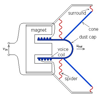
Example
Most interest in transducers focus on loudspeakers. In figure 4 below, the blue components are fully part of the moving mass of the system. The red components, primarily the spider, comprise the compliance of the system. Damping appears in many places: in contact areas inside the magnet's gap and also in the compliance components themselves.| Figure 4: Components of a
typical loudspeaker transducer |
 |
The electrical-mechanical circuit of figure 5 below show the mechanical elements in series.
| Figure 5: A simple
representation of a speakers electrical and mechanical circuits |
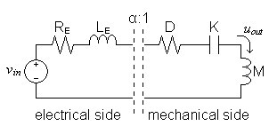 |
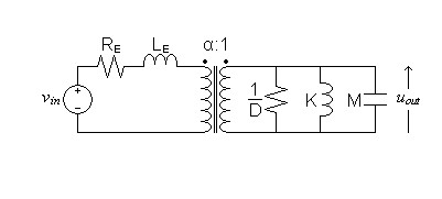
The electrical-side equivalent circuit of figure 6 below shows the mechanical impedances inverted as specified previously. Notice that the series mechanical topology is seen from the electrical side as a parallel circuit and the transducer interface is now represented as a simple transformer.
| Figure 6: Speaker circuit
with mechanical side converted to its electrical equivalent |
 |
|
|
1A. Bruce Carlson and David G. Gisser, Electrical Engineering: Concepts and Applications, (Reading 1981) p. 649 Use of α to represent force factor. Most other sources use the full form Bl.
Document History
April 27, 2013 Created.
April 27, 2013 Improved some aspects of appearance and wording, and corrected misspelling in image of figure 5.