 |
| Home │ Audio
Home Page |
Copyright © 2011 by Wayne Stegall
Created August 5, 2011. See Document History at end for
details.
Optimizing the Class B Emitter Follower
Is
current drive better than voltage drive?
Introduction
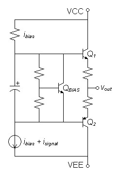
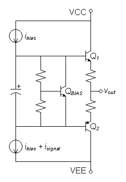
In an ordinary three stage class-b amplifier, the emitter follower output is driven by a class-a stage. If the immediate load to the class-a driver is a simple resistor of lower impedance than impedance seen at the bases of the emitter follower, it is obvious that the emitter-follower is voltage driven. It occurred to me that the common alternative to load the class-a output with a current source creates current drive to the emitter follower circuit and therefore a push-pull current output.If the current gain of the transistors were matched, it seems current drive would alleviate crossover distortion by the direct way the input current would be expected to drive an amplified current to the load. The input current would simply be driven as-is into the bases of the transistors to appear amplified without artifact to the output. The resistor load as an alternative would allow crossover distortion mechanisms full reign.
Presuming biases cancel at output and given input conditions:
isignal = ib1 + ib2
and that current gains match (βNPN = βPNP):
iout = β(ib1 + ib2)
iout = β(isignal)
Is this theory true?
To investigate I setup a SPICE deck modeling the class-a driver as a current signal source only, loaded as necessary to drive the emitter follower. This would eliminate all but the output stage as a source of distortion. I set the diode multiplier bias for a total of approximately 47mV across the two emitter resistors1 and the input signals for an ac output of 5V peak.
| Figure
1: Voltage driven emitter follower |
Figure
2:
Current
driven
emitter
follower
|
 |
 |
SPICE Results for Voltage Drive
Fourier analysis for vout:No. Harmonics: 16, THD: 4.63196 %, Gridsize: 1024, Interpolation Degree: 3
| Harmonic | Frequency | Magnitude | Norm.Mag | Percent | Decibels |
| -------- | --------- | --------- | --------- | --------- | --------- |
| 1 | 1000 | 5.30764 | 1 | 100 | 0 |
| 2 | 2000 | 0.118289 | 0.0222865 | 2.22865 | -33.03916261 |
| 3 | 3000 | 0.208687 | 0.0393182 | 3.93182 | -28.10812745 |
| 4 | 4000 | 0.00457183 | 0.000861368 | 0.0861368 | -61.29622533 |
| 5 | 5000 | 0.0499479 | 0.00941057 | 0.941057 | -40.52768141 |
| 6 | 6000 | 0.00538611 | 0.00101479 | 0.101479 | -59.87247642 |
| 7 | 7000 | 0.0171109 | 0.00322382 | 0.322382 | -49.8325843 |
| 8 | 8000 | 0.00432119 | 0.000814146 | 0.0814146 | -61.78595413 |
| 9 | 9000 | 0.0040359 | 0.000760395 | 0.0760395 | -62.37921495 |
| 10 | 10000 | 0.00188954 | 0.000356004 | 0.0356004 | -68.97090245 |
| 11 | 11000 | 0.00154618 | 0.000291313 | 0.0291313 | -70.71280269 |
| 12 | 12000 | 0.000202099 | 0.000038077 | 0.0038077 | -88.38674552 |
| 13 | 13000 | 0.00321911 | 0.000606504 | 0.0606504 | -64.34332661 |
| 14 | 14000 | 0.00127342 | 0.000239923 | 0.0239923 | -72.39856234 |
| 15 | 15000 | 0.0028606 | 0.00053896 | 0.053896 | -65.36886931 |
SPICE Results for Current Drive
Fourier analysis for vout:No. Harmonics: 16, THD: 12.5555 %, Gridsize: 1024, Interpolation Degree: 3
| Harmonic | Frequency | Magnitude | Norm.Mag | Percent | Decibels |
| -------- | --------- | --------- | --------- | --------- | --------- |
| 1 | 1000 | 4.92209 | 1 | 100 | 0 |
| 2 | 2000 | 0.206496 | 0.0419528 | 4.19528 | -27.54478097 |
| 3 | 3000 | 0.54593 | 0.110914 | 11.0914 | -19.10027264 |
| 4 | 4000 | 0.0529415 | 0.0107559 | 1.07559 | -39.36706488 |
| 5 | 5000 | 0.17918 | 0.0364032 | 3.64032 | -28.77720877 |
| 6 | 6000 | 0.012936 | 0.00262815 | 0.262815 | -51.60699703 |
| 7 | 7000 | 0.0724497 | 0.0147193 | 1.47193 | -36.64225686 |
| 8 | 8000 | 0.00127415 | 0.000258864 | 0.0258864 | -71.73856685 |
| 9 | 9000 | 0.0286507 | 0.00582083 | 0.582083 | -44.70030169 |
| 10 | 10000 | 0.000680928 | 0.000138341 | 0.0138341 | -77.18098179 |
| 11 | 11000 | 0.00867485 | 0.00176243 | 0.176243 | -55.07776247 |
| 12 | 12000 | 0.000639199 | 0.000129863 | 0.0129863 | -77.73029137 |
| 13 | 13000 | 4.62639E-05 | 9.39923E-06 | 0.000939923 | -100.5381545 |
| 14 | 14000 | 0.00244699 | 0.000497144 | 0.0497144 | -66.07035595 |
| 15 | 15000 | 0.00300727 | 0.000610974 | 0.0610974 | -64.27954542 |
Final Thoughts
It is a normal outcome of design to conceive some outcomes that prove
untrue. In this case the simpler resistor load wins out over the
topology theorized to give a lower open-loop distortion result.
Because current drive produces more gain than voltage drive, current
drive would be expected to produce lower distortion after applying
feedback however. Whether your design philosophy prefers the
lowest final distortion or the most linear open-loop result will
determine the final assessment of such results.|
|
1G. Randy Sloane, The Audiophile's Project Sourcebook,
p.182.
Author
recommends
47mV
bias
across
both
emitter
resistors
as
optimal bias apart from actual distortion measurements.
Document History
August 5, 2011 Created.